Arrest net device

A technology for weaving nets and projectiles is applied in the field of arresting net devices, which can solve the problems of long range, short range, and low capture accuracy of the arresting net, and achieve the effect of long range

Inactive Publication Date: 2015-04-22
关涛
View PDF6 Cites 0 Cited by
  • Summary
  • Abstract
  • Description
  • Claims
  • Application Information

AI Technical Summary

Problems solved by technology

[0003] The purpose of the present invention is to overcome the problems of the existing arresting net device, such as short shooting range, low arresting accuracy of the arresting net and poor reliability of arresting the arresting net, and provide a long-range, accurate arresting arresting net. The arresting net device with high performance and strong arresting reliability of the arresting net

Method used


Image

  • Arrest net device
  • Arrest net device
  • Arrest net device

Examples


Embodiment 1

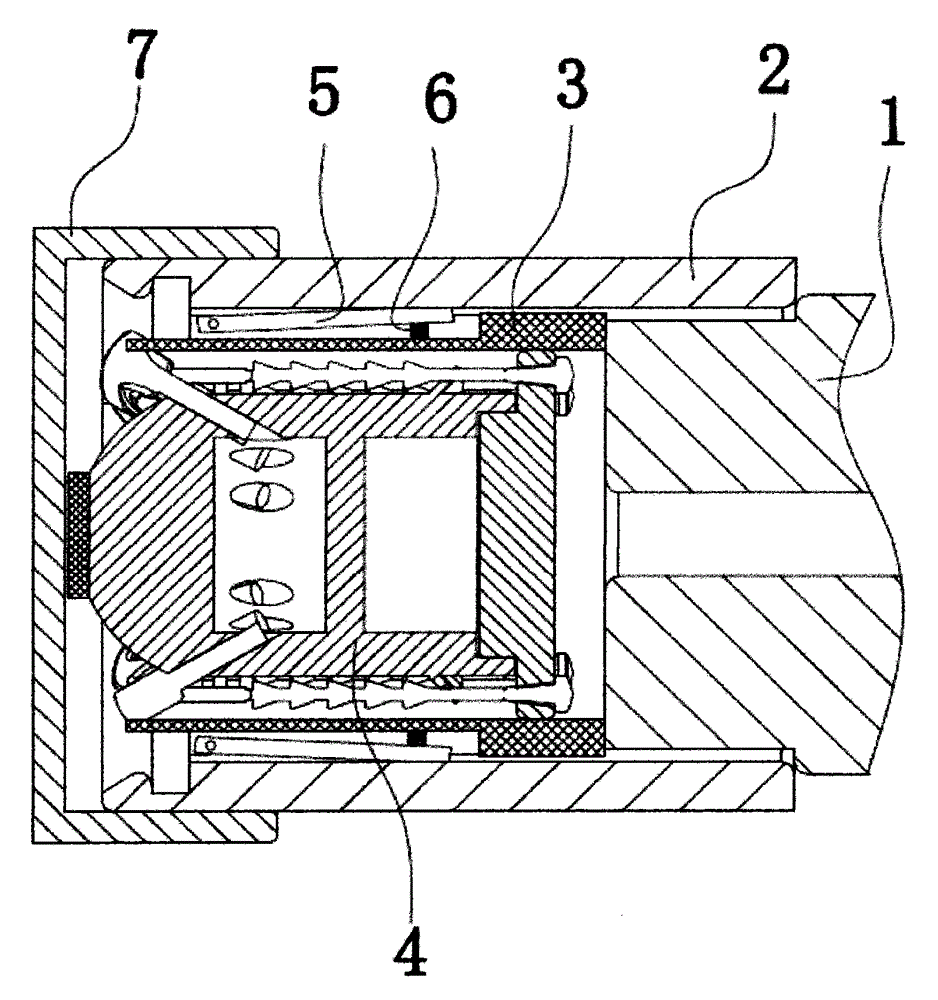
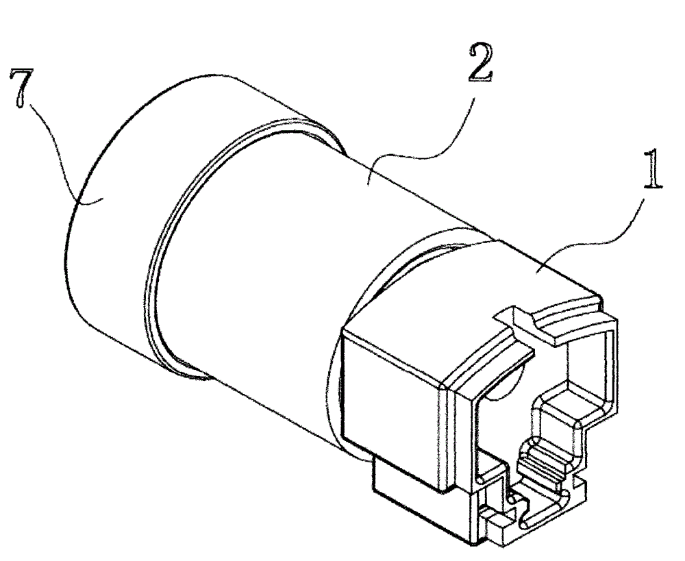
[0023] Embodiment 1: as figure 1 , figure 2 , image 3 Shown, a kind of arresting net device comprises fixed base 1, is arranged on the launch tube 2 of fixed base front end, projectile body 4, is sheathed in the projectile body sheath 3 outside the projectile body and is relatively arranged on projectile body 4 both sides Two sheets of braided nets 11. The projectile sheath 3 is located in the launch tube 2 . The material of the fixed base, the launch tube, the projectile sheath and the projectile is aluminum alloy. The fixed base 1 is provided with a through hole, and the front end of the fixed base is provided with a circular boss; the launch tube is sleeved on the circular boss, and the launch tube is locked on the circular boss by screws. A protective cover 7 is provided at the outer port of the launching tube 2 .

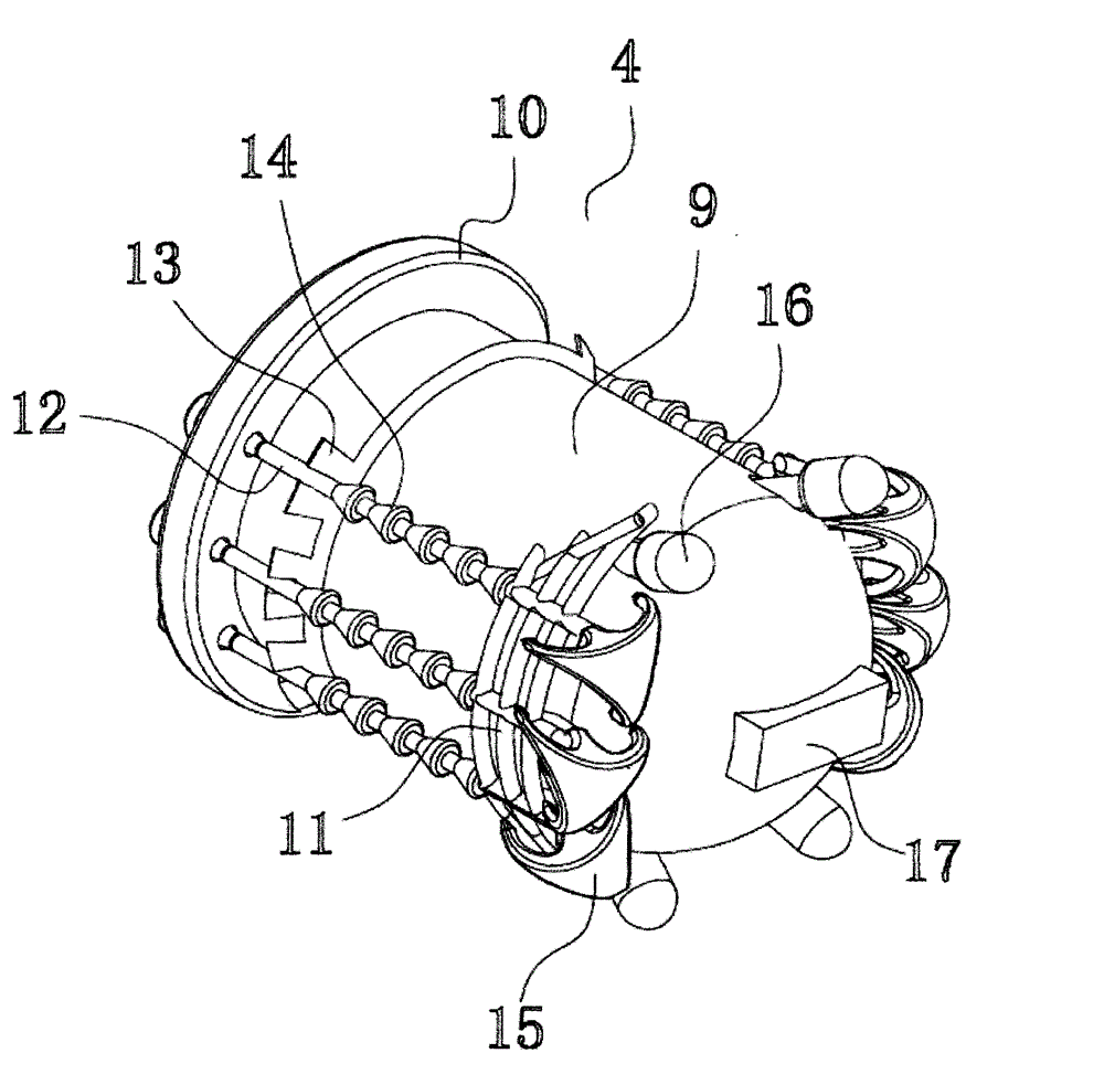
[0024] Such as Figure 4 As shown, the projectile body 4 includes a projectile body casing 9 and a projectile body rear cover 10 arranged at the rear p...

Embodiment 2

[0035] Embodiment 2: as Figure 5 Shown, a kind of arresting net device comprises multi-shot device 24. The multi-shot device includes a clip 25, which is provided with a vertical filling cavity 26 for filling the projectile sheath 3 and the projectile 4. The upper end of the vertical filling cavity 26 is open, that is, the vertical filling cavity 26 has an upper port. The bottom of the vertical filling chamber 26 is provided with a filling spring 27 . The clip 25 is arranged on the side wall of the launch tube 2, and the upper port of the vertical filling cavity 26 is opposite to the side wall of the launch tube, and the side wall of the launch tube 2 is provided with the vertical filling cavity. Corresponding notch on the port. The clip 25 is also provided with textures for handshaking. Refer to Embodiment 1 for the rest of the structure of this embodiment.

[0036] Through the multi-shot device of this embodiment, the arresting net device can be launched continuously t...


PUM


Abstract

The invention discloses an arrest net device, aiming at providing an arrest net device which is far in range, high in the arrest accuracy of an arrest net, and strong in the arrest reliability of the arrest net. The arrest net device comprises a projectile body, a projectile body sheath which is sleeved outside the projectile body and two woven nets which are oppositely arranged on the two sides of the projectile body, wherein the rear sides, which are close to the rear end of the projectile body, of the woven nets are connected with the rear end of the projectile body; the front ends, which are close to the front end of the projectile body, of the woven nets are at least provided with two anchor hooks which are connected with the woven nets; a first cavity is arranged in the projectile body and a detonating device is arranged in the first cavity; the outer side face of the projectile body is provided with inclined holes which correspond to the anchor hooks and are communicated with the first cavity; the inclined holes are arranged in the way of slantly outwards extending from the rear part of the projectile body to the front part of the projectile body; the anchor hooks are provided with anchor rods which are arranged in the corresponding inclined holes; a controller is arranged on the projectile body; and a signal emitting and receiving module is arranged at the front end of the projectile body.

Description

technical field [0001] The invention relates to an object catching device, in particular to an arresting net device with long shooting range and high arresting accuracy of the arresting net. Background technique [0002] In real life, it is very difficult for police officers to capture prisoners; in order to facilitate police officers to capture prisoners, improve the efficiency of capture, and effectively ensure the safety of police officers when arresting prisoners, arresting nets are usually used to assist Capture criminals. Present arresting net device has only one arresting net usually, and this arresting net is launched by transmitter, is also provided with connecting rope between arresting net and transmitter simultaneously. For example, the Chinese Patent Publication No. CN202083281U, the publication date was December 21, 2011. The name created by the utility model is the arresting net launching gun. The application discloses a arresting net launching gun, which inc...

Claims


Application Information

Patent Timeline
Patent Type & Authority Patents(China)
IPC IPC(8): F41B15/00
Inventor 关涛
Owner 关涛
Why Eureka
Try Eureka