Supercharge Your Innovation With Domain-Expert AI Agents!

Guidance mechanism for optical disc mold positioning

A technology of guiding mechanism and mold, applied in the field of guiding mechanism, can solve problems such as pressing mold, hidden danger, failure and aging of pressure spring 4', and achieve the effect of solving hidden safety hazard and production safety

Active Publication Date: 2016-04-06
KAIPING YINGGUANG ELECTROMECHANICAL TECH
View PDF5 Cites 0 Cited by
  • Summary
  • Abstract
  • Description
  • Claims
  • Application Information

AI Technical Summary

Problems solved by technology

[0003] However, in the process of producing optical discs, the movable mold needs to be opened and closed frequently, so the sleeve frame of the ball sleeve 2' is easy to wear and tear. If the sleeve frame of the ball sleeve 2' is worn and broken, it will be exposed outside the guide sleeve 1'. The balls on the ball sleeve 2' are likely to fall between the movable mold and the fixed mold, causing the die to be pressed, and seriously damaging the mold and its accessories. Compression spring 4', but in the process of long-term frequent mold opening and mold closing, compression spring 4' bears too many times of force in the opposite direction, which will cause compression spring 4' to fail and age, so the ball sleeve cannot be tightened 2', during the rapid mold opening process, the ball sleeve 2' is likely to move along with the guide post 3' in the direction away from the fixed mold. When the guide post 3' stops, the ball sleeve 2' continues to move along the The guide column moves towards the movable mold, so that it is exposed from the guide sleeve 1', so the balls on the ball sleeve 2' have a safety hazard of falling off

Method used


Image

  • Guidance mechanism for optical disc mold positioning
  • Guidance mechanism for optical disc mold positioning

Examples


Embodiment Construction

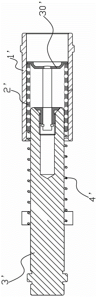
[0014] refer to figure 2 , the guide mechanism used for the positioning of the optical disc mold, including a guide sleeve 1 fixedly installed on the fixed mold, the inside of the guide sleeve 1 is movably embedded with a ball sleeve 2, and the inside of the ball sleeve 2 is movable. The guide post 3 on the movable mold, the inside of the ball sleeve 2 is fixedly provided with a wear-resistant ring 4 sleeved on the guide post 3, and the gap between the wear-resistant ring 4 and the guide post 3 is The ball sleeve 2 is fixed on the guide post 3, so the guide post 3 drives the ball sleeve 2 to move toward or away from the fixed mold in the guide sleeve 1. When the guide post 3 stops, the ball sleeve 2 It will also stop immediately and will not continue to move forward. Therefore, when the guide post 3 stops, the ball sleeve 2 can be prevented from being exposed from the guide sleeve 1 by continuing to move forward along the guide post 3 due to inertia, because The ball sleeve ...


PUM


Abstract

The invention discloses a guide mechanism for positioning a light disk module. The guide mechanism comprises a guide sleeve fixedly arranged on a fixed module, wherein the guide sleeve is internally and movably embedded with a ball sleeve; a guide post fixed on a moving module is movably arranged in the ball sleeve in a penetrating manner, the ball sleeve is internally fixedly provided with a wear-resisting ring sleeved on the guide post, and the wear-resisting ring is in interference fit with the guide post. According to the guide mechanism provided by the invention, the wear-resisting sleeve is in interference fit with the guide post through a wear-resisting sleeve sleeved on the guide post in the ball sleeve, and thus, when the moving module opens and moves to a presetting position, and the guide post is immediately stopped; the wear-resisting sleeve is in interference fit with the guide post, and thus, the wear-resisting sleeve is limited by the guide post so as to not unceasingly outward shift, so that the ball sleeve fixedly connected with the wear-resisting sleeve is immediately stopped, and a condition that the ball sleeve can not be exposed outside the guide sleeve is guaranteed.

Description

technical field [0001] The invention relates to a guiding mechanism of a disc mold. Background technique [0002] As we all know, the production of optical discs needs to use a fixed mold fixedly installed on the machine tool. The fixed mold is equipped with a movable mold that can form a mold with it or be separated from each other independently through a positioning mechanism. The above-mentioned positioning mechanism is specifically as follows: Refer to the attached figure 1 , the positioning mechanism includes a guide sleeve 1' fixedly installed on the fixed mold, the guide sleeve 1' is movably embedded with a ball sleeve 2', and the inside of the ball sleeve 2' is movable and fixedly installed on the movable mold. The guide post 3' on the guide post 3' is provided with a compression spring 4' for tightening the ball sleeve 2' and preventing it from being exposed from the end of the guide sleeve 1' close to the movable die. One end of the column 3' close to the fixed mo...

Claims


Application Information

Patent Timeline
Patent Type & Authority Patents(China)
IPC IPC(8): B29C33/20
Inventor 张书庭
Owner KAIPING YINGGUANG ELECTROMECHANICAL TECH
Features
  • R&D
  • Intellectual Property
  • Life Sciences
  • Materials
  • Tech Scout
  • Unparalleled Data Quality
  • Higher Quality Content
  • 60% Fewer Hallucinations
Learn More