
Bandage

A technology of straps and bosses, applied in the direction of electrical components, etc., can solve the problems of being easily wound into a mess, inconvenient to use, etc., and achieve the effects of avoiding loss, reasonable structure, and low cost

Inactive Publication Date: 2013-09-25
苏州苏越电气有限公司
View PDF6 Cites 1 Cited by
  • Summary
  • Abstract
  • Description
  • Claims
  • Application Information

AI Technical Summary

Problems solved by technology

[0002] Existing wired devices, such as mice, earphones, chargers, etc. all have long cables, which are easily tangled into a mess when carried and stored, which is quite inconvenient to use

Method used


Image

  • Bandage
  • Bandage
  • Bandage

Examples


Embodiment Construction

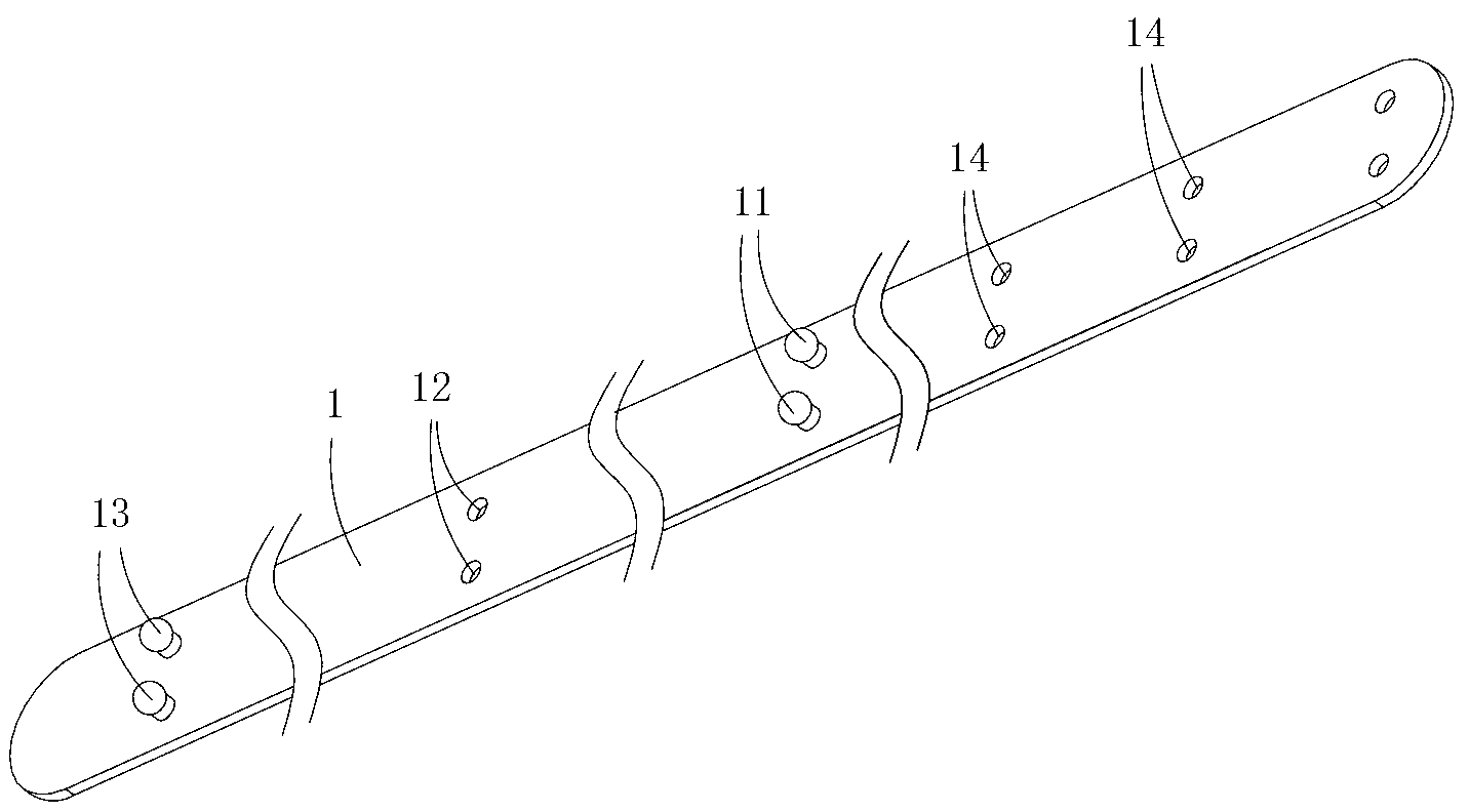
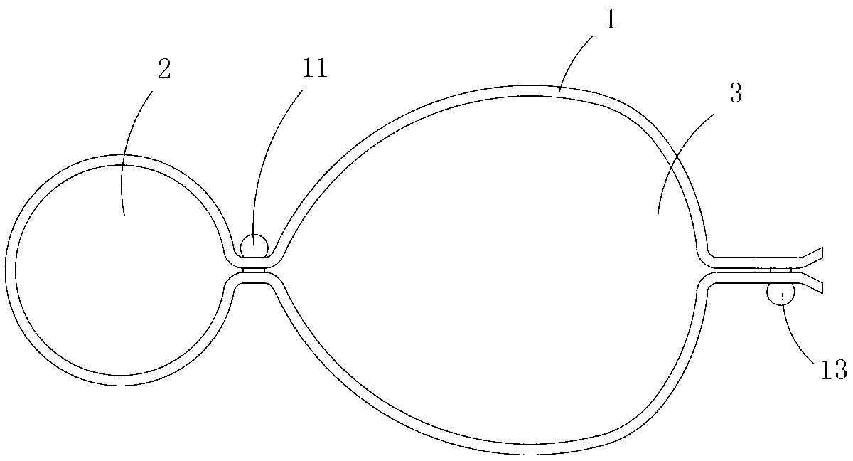
[0012] Figure 1 to Figure 4 A specific embodiment of the invention is shown in which, figure 1 It is a schematic diagram of a three-dimensional structure of the present invention; figure 2 yes figure 1 A cross-sectional view of the strap shown; image 3 yes figure 1 A front view of the strap shown after forming the first clip hole and the second clip hole; Figure 4 yes image 3 An application diagram of the strap shown.

[0013] This embodiment is a strap, see Figure 1 to Figure 4 As shown, it includes a strip-shaped plate body 1, and the plate body is sequentially provided with a second clamping boss 13, a first clamping hole 12, and a first clamping hole matched with the first clamping hole along the direction from one end to the other end. Connecting the boss 11, and the second clamping hole 14 matched with the second clamping boss; the first clamping boss and the second clamping boss are located at the same side end of the plate body; the first clamping boss cla...


PUM


Abstract

The invention discloses a bandage which comprises a strip-shaped plate, wherein second clamping bosses, first clamping holes, first clamping bosses matched with the first clamping holes, and second clamping holes matched with the second clamping bosses are sequentially arranged on the plate along the direction from one end to the other end; the first clamping bosses and the second clamping bosses are positioned on the same side of the plate; after the first clamping bosses are clamped in the first clamping holes, the first clamping bosses and plate between the first clamping holes are encircled to form a first clip hole; after the second clamping bosses are clamped in the second clamping holes, the second clamping bosses and plate between the second clamping holes are encircled to form a second clip hole. The bandage has the advantages that the bandage is convenient to use, and cables can be neatly strapped.

Description

technical field [0001] The invention belongs to the technical field of binding, and in particular relates to a binding belt. Background technique [0002] Existing wired devices, such as mice, earphones, chargers, etc., all have long cables, which are easily tangled into a mess when carried and stored, which is quite inconvenient to use. Contents of the invention [0003] The purpose of the present invention is to provide a binding strap that is convenient to use and can bundle cables neatly. [0004] The technical solution for realizing the present invention is: a strap, comprising a strip-shaped plate body, on which the second clamping boss, the first clamping hole, and the first clamping hole are sequentially provided along the direction from one end to the other end. The first clamping boss matched with the hole, and the second clamping hole matched with the second clamping boss; the first clamping boss and the second clamping boss are located on the same ...

Claims


Application Information

Patent Timeline
Patent Type & Authority Applications(China)
IPC IPC(8): H02G3/04
Inventor 黄海林
Owner 苏州苏越电气有限公司
Learn More