
pneumatic vehicle

A pneumatic vehicle and exhaust gas technology, applied to vehicle components, brakes, power devices, etc., can solve the problems of limited cruising range, inability to maximize the use of braking energy, quantitative control of braking energy recovery, etc., to improve battery life Mileage, the effect of improving overall operating efficiency

Active Publication Date: 2016-08-17
LUCKSKY HLDG GRP
View PDF12 Cites 0 Cited by
  • Summary
  • Abstract
  • Description
  • Claims
  • Application Information

AI Technical Summary

Problems solved by technology

However, this kind of pneumatic vehicle does not effectively carry out precise quantitative control on the recovery and utilization of braking energy, resulting in that the braking energy cannot be utilized to the maximum extent, and the cruising range is limited to a certain extent, which affects the overall operating efficiency of the pneumatic vehicle.

Method used


Image

  • pneumatic vehicle
  • pneumatic vehicle
  • pneumatic vehicle

Examples


Embodiment Construction

[0034] The following description is merely exemplary in nature and not intended to limit the disclosure, application or use. It should be understood that throughout the drawings, corresponding reference numerals indicate like or corresponding parts and features. These and other aspects of embodiments of the invention will become apparent with reference to the following description and drawings. In these descriptions and drawings, some specific implementations of the embodiments of the present invention are specifically disclosed to represent some ways of implementing the principles of the embodiments of the present invention, but it should be understood that the scope of the embodiments of the present invention is not limited by this limit. On the contrary, the embodiments of the present invention include all changes, modifications and equivalents coming within the spirit and scope of the appended claims.

[0035] Referring now to the accompanying drawings, figure 1 A prefe...


PUM


Abstract

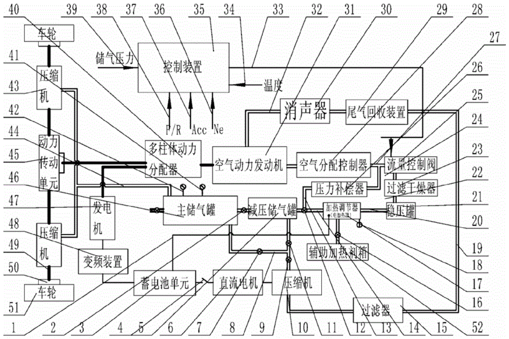
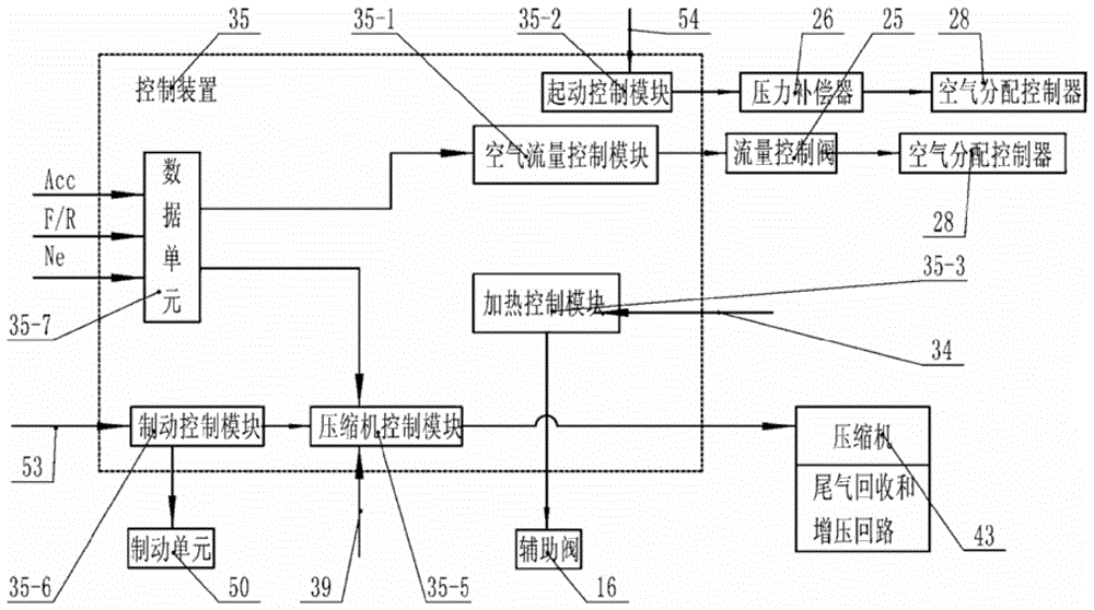
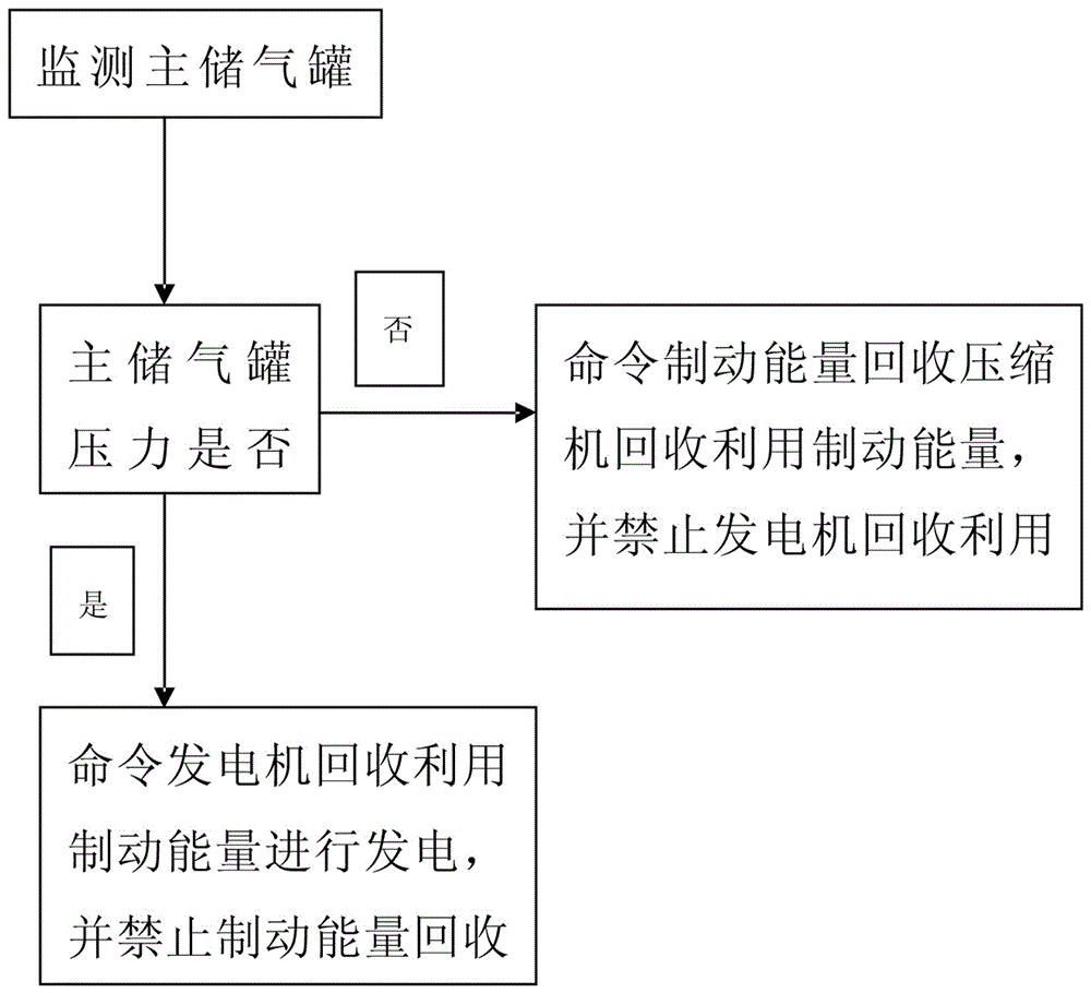
The invention provides a pneumatic vehicle which comprises a main gas storage tank, a decompression gas storage tank, a generator, a storage battery unit, a direct current motor, a braking energy recovery compressor, a tail gas booster compressor, a main gas storage tank pressure monitoring device and a control device. When the vehicle is in braking, the braking energy recovery compressor can selectively recycle braking energy to generate compressed gas. The direct current motor drives the tail gas booster compressor to work for boosting the pressure of recovered tail gas. The control device receives a pressure value supplied by the main gas storage tank pressure monitoring device; when the pressure value is larger than a preset threshold value, the control device orders the generator to recycle the braking energy for power generation and prohibits the braking energy recovery compressor from recycling the braking energy; when the pressure value is smaller than the preset threshold value, the control device orders the braking energy recovery compressor to recycle the braking energy and prohibits the generator from recycling the braking energy for power generation. The pneumatic vehicle can accurately control the recycling of the braking energy sufficiently and effectively, and therefore the continuous driving mileage of the vehicle is increased.

Description

technical field [0001] The invention relates to a pneumatic vehicle, in particular to a pneumatic vehicle capable of fully recovering and utilizing braking energy. Background technique [0002] Most ground vehicles, such as automobiles, trucks, and off-road vehicles, use internal combustion engines that use fuel as a working medium as their power source. On the one hand, this kind of engine using fuel oil as a working medium pollutes the environment due to insufficient combustion of fuel oil, so that the discharged gas contains a large amount of harmful substances and pollutes the environment. The shortage makes the development and utilization of fuel engines more and more restricted. Therefore, developing new, clean, non-polluting alternative energy sources and using this alternative energy source as the power source of ground vehicles has become an urgent problem to be solved in the development of modern vehicles. Pneumatic vehicles are just suitable for this need and gra...

Claims


Application Information

Patent Timeline
Patent Type & Authority Patents(China)
IPC IPC(8): B60K8/00B60T13/10
Inventor 周登荣周剑
Owner LUCKSKY HLDG GRP
Learn More