Yarn lifting mechanism for waste yarn collection

A technology of waste yarn and driving mechanism, which is applied to auxiliary equipment for weaving, textiles, textiles, and papermaking. It can solve the problems of waste thread ends floating to other places to pollute workshops, waste thread ends that cannot be sucked away, and difficult to collect, so as to increase energy consumption. The effect of utilization

Active Publication Date: 2015-01-28
苏州华哥电器科技有限公司
View PDF5 Cites 0 Cited by
  • Summary
  • Abstract
  • Description
  • Claims
  • Application Information

AI Technical Summary

Problems solved by technology

However, in the cutting process, there is always a part of discarded weft thread cut off, and it is often not easy to collect these discarded thread ends, because usually the discarded thread ends are very short and light, and are not easy to collect, and some looms may be equipped with waste Yarn collection mechanism, but the existing waste yarn collection mechanism uses negative pressure dust suction type, but because these discarded thread ends are very light, the dust-absorbing waste yarn collection mechanism may not be able to completely absorb all waste thread ends Go, some waste threads may float to other places to pollute the workshop, and may also enter the interior of the machinery and equipment to cause adverse effects
And the use of dust-absorbing waste yarn collection mechanism will increase some necessary supporting facilities, increasing the cost

Method used


Image

  • Yarn lifting mechanism for waste yarn collection
  • Yarn lifting mechanism for waste yarn collection
  • Yarn lifting mechanism for waste yarn collection

Examples


Embodiment 1

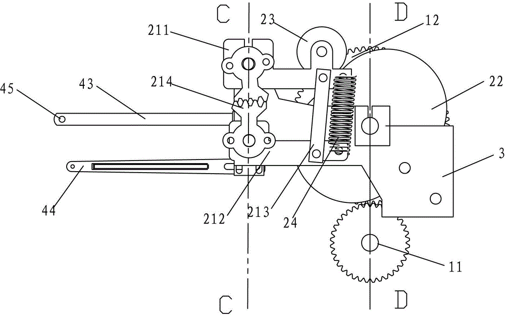
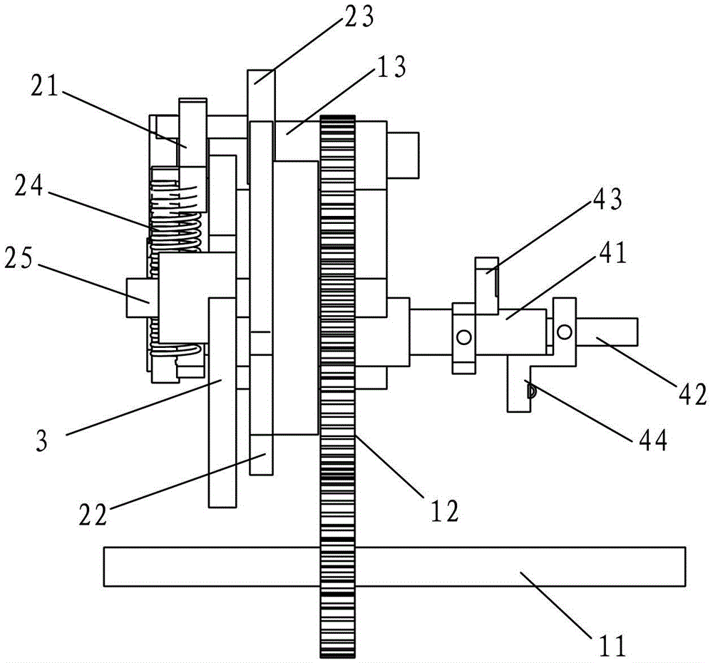
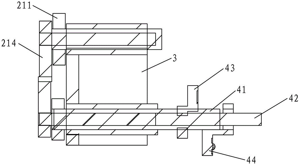
[0022] Such as Figure 1-4 As shown, the present invention discloses a yarn lifting mechanism for waste yarn collection, which includes a driving mechanism 1, a transmission mechanism 2, a mounting plate 3 and a nip 4, and the transmission mechanism 2 includes an eccentric rotatably mounted on the mounting plate 3. Wheel 22, the pinch wheel 23 that is arranged on the eccentric wheel 22 edges, the return spring 24 that is used to reset the pinch wheel 23, the link mechanism 21 that is connected with the pinch wheel 23, the jaw 4 includes being fixedly arranged on the upper and lower pinch bar shafts ( 41,42) on the upper and lower clamping rods (43,44), the ends of the upper and lower clamping rods (43,44) are provided with through holes 45, and the rotation of the upper and lower clamping rod shafts (41,42) is arranged on the installation plate 3.

[0023] The link mechanism 21 includes a first transmission rod 211, a second transmission rod 212, a connecting rod 213, and a b...


PUM


Abstract

The invention discloses a yarn lifting mechanism for waste yarn collection. The yarn lifting mechanism comprises a driving mechanism, a transmission mechanism, a mounting plate and a clamping mouth, wherein the driving mechanism comprises an eccentric wheel, a pressing wheel, a reset spring and a link mechanism; the eccentric wheel is mounted on the mounting plate, the pressing wheel is arranged on the edge of the eccentric wheel, the reset spring is used for resetting the pressing wheel, and the link mechanism is connected with the pressing wheel; the clamping mouth comprises an upper clamping rod and a lower clamping rod which are fixedly arranged on an upper clamping rod shaft and a lower clamping rod shaft; the upper clamping rod shaft and the lower clamping rod shaft are rotationally arranged on the mounting plate; through holes are formed in end parts of the upper clamping rod and the lower clamping rod; and when the driving mechanism operates, the eccentric wheel is driven to rotate, the eccentric wheel moves up and down under transmission, and the link mechanism is under the transmission of the eccentric wheel and drives the upper clamping rod shaft and the lower clamping rod shaft to move synchronously in opposite directions, so that the upper clamping rod and the lower clamping rod move crosswise, and yarn arranged in the through holes twists the waste yarn. The yarn lifting mechanism for waste yarn collection can collect waste yarn in a loom production process simply and effectively.

Description

technical field [0001] The invention relates to a loom waste yarn collection mechanism, in particular to a yarn lifting mechanism for waste yarn collection. Background technique [0002] In the textile industry, various types of looms are widely used, such as rapier looms, air-jet looms, water-jet looms, projectile looms, etc. Different looms work in different ways and are suitable for different fabrics. In today's era of modernization and mechanized production, efficiency is also very important while ensuring quality. Therefore, air-jet looms and water-jet looms are widely used in ordinary textile enterprises to achieve high productivity. [0003] However, since the air-jet loom or water-jet loom is working, the weft thread is drawn into the shed by compressed air or high-pressure water flow. When a weft thread finishes passing through all the warp threads, it will be cut off, and then the weft thread will be repeatedly pulled. During the weaving process, there are many cu...

Claims


Application Information

Patent Timeline
Patent Type & Authority Patents(China)
IPC IPC(8): D03J1/04
Inventor 计剑华叶玉行
Owner 苏州华哥电器科技有限公司
Why Eureka
Try Eureka