
Automatic peritoneal dialysis device

A technology of peritoneal dialysis and peritoneal dialysis solution, which is applied in the field of automatic peritoneal dialysis devices, can solve problems such as difficulty and dislocation, and achieve the effect of improving insertion

Active Publication Date: 2013-10-23
TERUMO KK
View PDF7 Cites 3 Cited by
  • Summary
  • Abstract
  • Description
  • Claims
  • Application Information

AI Technical Summary

Benefits of technology

This patented technology allows for easier access when needed without requiring manual adjustment or special equipment like this one described earlier. It makes sure there are no mistakes made while installing new tubes into the machine's parts after each treatment session.

Problems solved by technology

This patents describes how current methods involve inserting new disposables during medical procedures like peritoning without any technical problem addressed in previous versions.

Method used


Image

  • Automatic peritoneal dialysis device
  • Automatic peritoneal dialysis device
  • Automatic peritoneal dialysis device

Examples


Embodiment Construction

[0053] Hereinafter, preferred embodiments of the present invention will be specifically described with reference to the drawings.

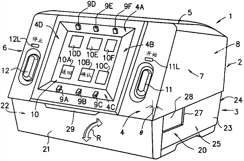
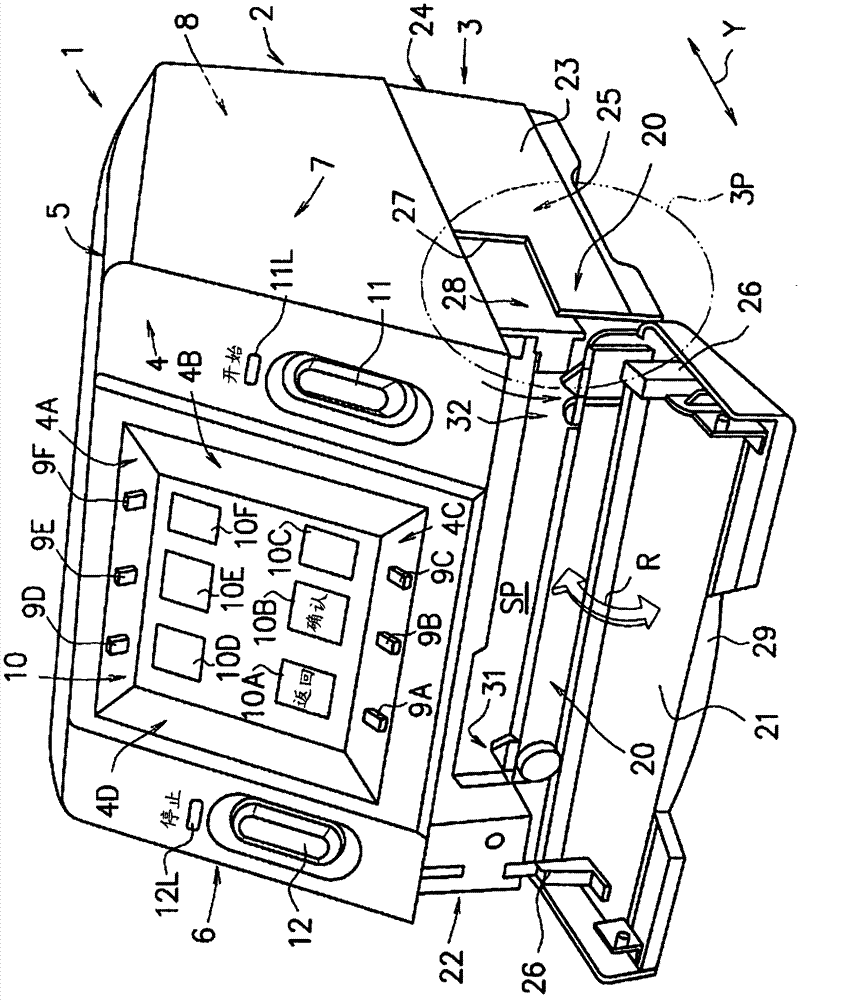
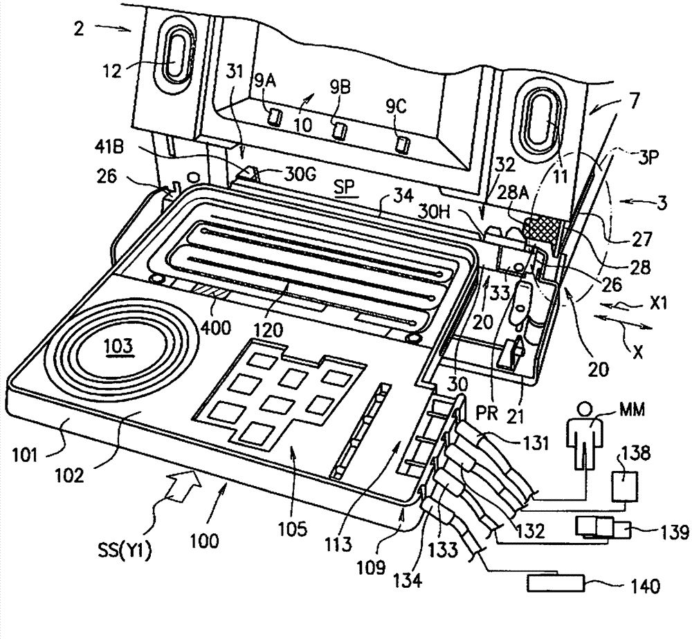
[0054] In addition, since the embodiment described below is a suitable specific example of the present invention, various technically preferable limitations are given, but the scope of the present invention is not limited to the meaning that the present invention is particularly limited in the following description. records, and are not limited to these methods. figure 1 with figure 2 is a perspective view showing a preferred embodiment of the automatic peritoneal dialysis apparatus of the present invention, figure 1 It is a perspective view which shows the state which closed the cover member of the dialysis cassette installation part of the automatic peritoneal dialysis apparatus, figure 2 It is a perspective view which shows the state which opened the cover member of the dialysis cassette installation part of the automatic peritoneal dialysi...


PUM


Abstract

The invention provides an automatic peritoneal dialysis device. A newly used dialysis box can be smoothly mounted on a correct set position inside a dialysis box mounting portion during dialysis by users such as a patient using the automatic peritoneal dialysis device, so that the inserting performance of the dialysis box can be improved. The automatic peritoneal dialysis device comprises the dialysis box (100) and the dialysis box mounting portion (20) for detachably mounting the dialysis box along an inserting direction (SS), the dialysis box mounting portion (20) comprises a first stop pin (31) of an inclined plane portion (41B) and a second stop pin (32) of an inclined groove portion (48), the inclined plane portion (41B) is used for contacting with the inner side (99D) of the first end side of the dialysis box to guide the dialysis box into dialysis box mounting portion (20) along the inserting direction (SS) when the dialysis box (100) is mounted on the dialysis box mounting portion (20), and the inclined groove portion (48) is used for guiding the second end (99F) of the dialysis box (100) into the dialysis box mounting portion (20) along the inserting direction (SS) in an embedded state when the dialysis box (100) is mounted on the dialysis box mounting portion (20).

Description


Claims


Application Information

Patent Timeline
Owner TERUMO KK
Learn More