
Inter-equipment fiber conveying device

A technology of conveying device and equipment room, which is applied in the field of fiber conveying device between equipment to achieve the effects of convenient maintenance, increased output and increased profit

Inactive Publication Date: 2013-10-23
常涛
View PDF5 Cites 2 Cited by
  • Summary
  • Abstract
  • Description
  • Claims
  • Application Information

AI Technical Summary

Problems solved by technology

[0005] 1. The three series of fans are all single-suction

Method used


Image

  • Inter-equipment fiber conveying device
  • Inter-equipment fiber conveying device

Examples


Embodiment Construction

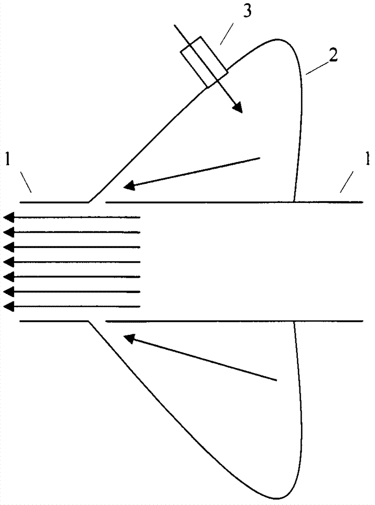
[0015] exist figure 1 In the middle, the high-pressure airflow enters the airflow directional conveyor (2) from the high-pressure airflow inlet (3), and the high-speed airflow is ejected from the 1mm outlet formed with the pipe, which produces a 15-fold amplification effect and forms a powerful airflow in the pipe (1). Fibers convey airflow.

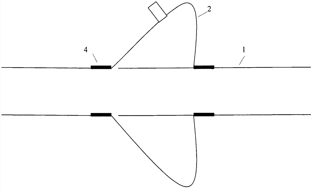
[0016] exist figure 2 Among them, the fiber conveying device between equipment is set on the pipeline (1) by the airflow directional conveyor (2), the 1mm outlet formed by the airflow directional conveyor (2) and the pipeline (1), and the sealing ring (4) realizes the airflow directional conveyor (2) The tightness ensures that the airflow is ejected from the outlet.


PUM


Abstract

Disclosed is an inter-equipment fiber conveying device by which overall conveying efficiency can be improved, energy consumption can be lowered and yield can be increased. The inter-equipment fiber conveying device is composed of a pipeline, an airflow directional conveyor and sealing rings. High-pressure airflow of a textile workshop is utilized, the airflow directional conveyor is connected, an outlet of the airflow directional conveyor is 1mm, when airflow is ejected, fifteen times of amplifying effect can be generated, strong fiber conveying airflow is formed in the pipeline, and if inter-equipment distance is large, two or more airflow directional conveyors can be arranged in a relay manner to enable fibers to smoothly reach specified equipment to complete conveying of the fibers well. By the inter-equipment fiber conveying device, the fibers can be conveyed efficiently, energy consumption can be lowered, the pipeline cannot be blocked, yield can be increased, profit can be increased; the inter-equipment fiber conveying device is simple in structure and convenient to maintain.

Description

Technical field [0001] The invention relates to a fiber conveying device between equipments, in particular to a conveying device capable of improving the overall conveying efficiency, reducing energy consumption, increasing output and increasing profit. Background technique [0002] Internationally, the research and development of the fan conveying system for fiber conveying between equipments began many years ago. Over the years, no matter the principle of the fan conveying system between The application of fan conveying pipe size between cleaning equipment, etc.) has made fruitful progress. [0003] The models of the fan conveying system for fiber conveying among several domestic cotton opening and cleaning equipment: SHX series fiber conveying fan, SYWS series fiber conveying fan, XWS series fiber material conveying fan. [0004] SHX series fiber conveying fans can be widely used to convey materials, air and gases that are non-corrosive, non-self-igniting, and non-viscou...

Claims


Application Information

Patent Timeline
IPC IPC(8): B65G53/16
Inventor 常涛
Owner 常涛
Learn More