Induction cooker coil plate bracket

A technology for coil discs and induction cookers, which is applied to coil devices, household stoves/stoves, electric heating fuels, etc., can solve the problems of inconsistent relative distances, changes in relative distances, and deterioration of the electrical performance of induction cookers, and achieves uniform and stable distances. Stable electrical performance, good for ventilation and heat dissipation

Inactive Publication Date: 2013-10-23
广东易爱云厨科技股份有限公司
View PDF4 Cites 1 Cited by
  • Summary
  • Abstract
  • Description
  • Claims
  • Application Information

AI Technical Summary

Problems solved by technology

[0002] At present, in the field of induction cooker manufacturing in our country, there are various structural forms of the concave induction cooker coil plate support, but most of the structures cannot ensure that the distance between the coil winding and the microcrystalline plate is strictly consistent, so that the electrical parameters of the coil plate are consistent The performance is not good, which brings difficulties to the adjustment of the whole machine of the induction cooker, and then affects the performance of the whole machine of the induction cooker
[0003] Some enterprises use the coil plate support with wire slots on the concave surface, relying on the bottom line slot wall to maintain the predetermined relative distance, but when the temperature of the coil plate rises, the coil plate support is easy to deform, causing the relative distance to change; and when the temperature is too high At the same time, because the coil disc bracket is made of plastic, it is easy to soften the plastic base material and cause permanent deformation, so that the relevant distance deviates from the set value, and the electrical performance of the induction cooker is completely deteriorated; some companies use simple glass fiber brackets. Bundle the wires in sections, and then hang them under the cooker with a hanger. The relative distance of each point in the circumferential direction of the coil disk is greatly inconsistent. When the vibration or temperature rise is slightly large, it is easy to deform and shift, and the electrical performance of the induction cooker will also deteriorate.

Method used


Image

  • Induction cooker coil plate bracket
  • Induction cooker coil plate bracket
  • Induction cooker coil plate bracket

Examples


Embodiment 1

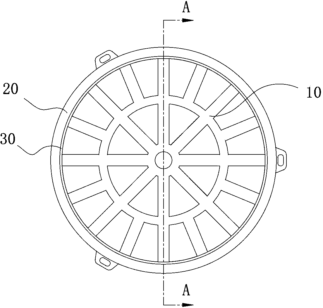
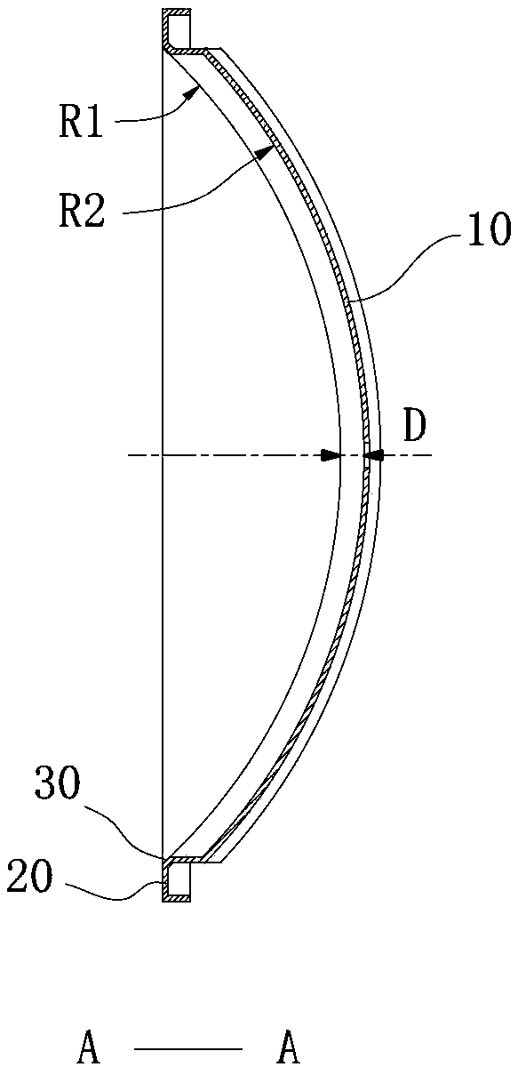
[0027] Such as figure 1 , Figure 2A , Figure 2B As shown, the coil disc support for an induction cooker according to Embodiment 1 of the present invention includes an inner coil disc 10 for arranging a coil winding 100 and an outer ring 20 located outside the inner coil disc 10 . Wherein, the upper end surface of the outer ring 20 is a plane, and an outer ring slope 30 for limiting the distance between the coil winding 100 and the microcrystalline plate 200 is provided at the connection between the inner surface of the inner ring disc 10 and the outer ring 20, and the inner ring disc 10 Both the inner surface and the bevel 30 of the outer ring are curved surfaces. Preferably, the inner surface of the inner ring disc 10 and the bevel 30 of the outer ring are both spherical surfaces with the same spherical center, and the radius R2 of the spherical crown of the inner ring disc 10 is greater than that of the bevel of the outer ring The spherical cap radius R1 of 30, and the r...

Embodiment 2

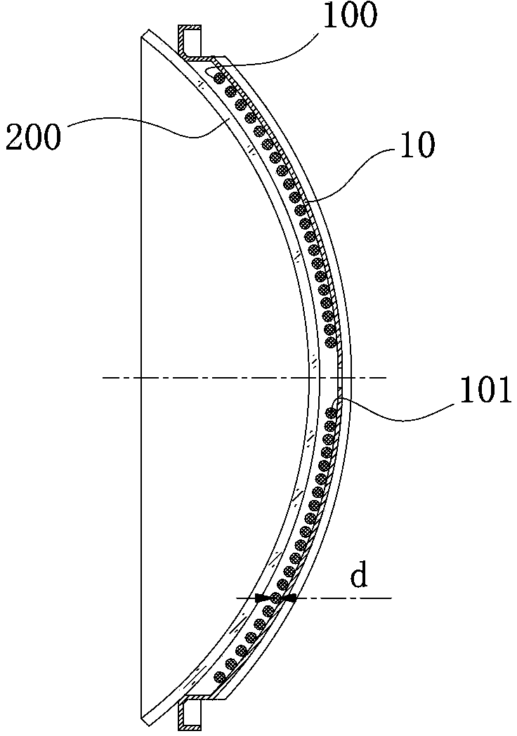
[0030] combine figure 1 and image 3 , Figure 4 , Figure 5 As shown, the difference between this embodiment and Embodiment 1 is that several grooves 11 are provided on the inner ring disc 10, and magnetic strips 12 are arranged in the grooves 11, and magnetic strips 12 are arranged on the grooves 11. Pressing plate 13 on bar 12 top. Specifically, the groove 11 is a U-shaped groove, the width of the U-shaped groove is greater than the width of the magnetic strip 12, the distance from the bottom of the U-shaped groove to the pressing plate 13 is greater than the thickness of the magnetic strip 12, and the distance between the magnetic strip 12 and the groove 11 Filled with binder. Now ensure that the width of the U-shaped groove 11 is slightly greater than the width of the magnetic strip 12; the groove 11 is fixedly provided with a pressing plate 13 positioned at the top of the magnetic strip 12, and the distance from the bottom of the U-shaped groove 11 to the pressing pl...


PUM


Abstract

The invention discloses an induction cooker coil plate bracket. The induction cooker coil plate bracket comprises an inner coil plate and an outer ring, the inner coil plate is used for installing a coil winding and a microcrystalline plate; the outer ring is arranged outside the inner coil plate; an outer circle slope is arranged at the joint of the inner surface of the inner coil plate and the outer ring; and the outer circle slope is used for limiting the distance between the coil winding and the microcrystalline plate. According to the induction cooker coil plate bracket, the outer circle slope used for limiting the distance between the coil winding and the microcrystalline plate is arranged at the joint of the inner surface of the inner coil plate and the outer ring; the inner surface of the inner coil plate and the outer circle slope are both curved surfaces; and through the matched installation of the microcrystalline plate and the outer circle slope, the distance between the coil winding and the microcrystalline plate is kept uniform and stable under the limiting effect of the outer circle slope, so that the electric performance of the coil plate is stable.

Description

technical field [0001] The invention relates to the coil disk technology of an electromagnetic cooker, in particular to a coil disk support for an electromagnetic cooker. Background technique [0002] At present, in the field of induction cooker manufacturing in our country, there are various structural forms of the concave induction cooker coil plate support, but most of the structures cannot ensure that the distance between the coil winding and the microcrystalline plate is strictly consistent, so that the electrical parameters of the coil plate are consistent The performance is not good, which brings difficulties to the adjustment of the whole machine of the induction cooker, and then affects the performance of the whole machine of the induction cooker. [0003] Some enterprises use the coil plate support with wire grooves on the concave surface, relying on the bottom wire groove wall to maintain the predetermined relative distance, but when the temperature of the coil pl...

Claims


Application Information

Patent Timeline
Patent Type & Authority Applications(China)
IPC IPC(8): H05B6/36F24C7/06
Inventor 樊东明卢海宝夏星星唐龙华
Owner 广东易爱云厨科技股份有限公司
Why Eureka
Try Eureka