Electric parking brake

An electronic parking brake and electronic parking technology, which is applied in the direction of brakes, brake actuators, gear transmission mechanisms, etc., can solve problems such as inability to perform brakes, unfavorable operating noise, and complex structures.

Inactive Publication Date: 2013-10-30
HL MANDO CORP
View PDF8 Cites 19 Cited by
  • Summary
  • Abstract
  • Description
  • Claims
  • Application Information

AI Technical Summary

Problems solved by technology

[0008] However, as mentioned above EPB uses one motor 3 and thus may require high voltage
In addition, since it is adapted to transmit the driving force to the speed reducer 8 through the gear assembly 7, it may have a complicated structure and be disadvantageous in terms of operational noise during braking
[0009] Furthermore, mounting the EPB to the vehicle may be limited because the motor 3 is arranged on one side of the caliper housing 2
[0010] In addition, if the motor 3 fails, braking cannot be performed

Method used


Image

  • Electric parking brake
  • Electric parking brake
  • Electric parking brake

Examples


Embodiment Construction

[0029] Reference will now be made in detail to embodiments of the invention, examples of which are illustrated in the accompanying drawings. It should be understood that the terms used in the specification and appended claims should not be construed as limited to the general and dictionary meanings, but should be understood based on the meanings and concepts according to the spirit of the present invention, which is based on the inventor Principles are allowed to define appropriate terminology for best interpretation. The preferred embodiments described in the specification and shown in the drawings are illustrative only and are not intended to represent all aspects of the invention, so that various equivalents and modifications may be made without departing from the spirit of the invention. transform.

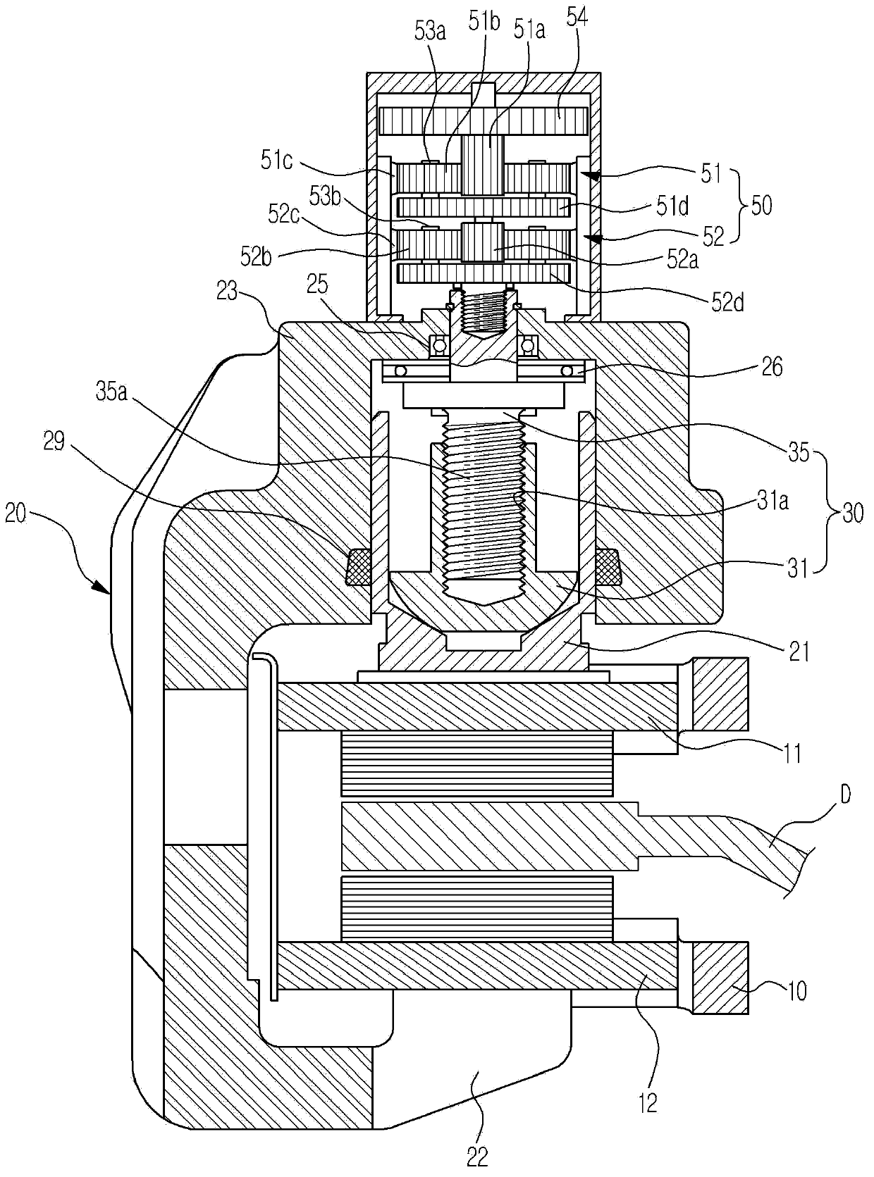
[0030] figure 2 is a side sectional view showing an electronic parking brake (EPB) according to an exemplary embodiment of the present invention, and image 3 is shown f...


PUM


Abstract

Disclosed is an electric parking brake (EPB). The EPB includes a carrier at which a pair of pad plates is installed, a caliper housing slidably installed at the carrier and provided with a cylinder in which a piston is installed, a spindle member arranged through a rear wall of the caliper housing and adapted to rotate, a pressing device provided with a nut member screw-coupled with the spindle member to apply pressure and release pressure applied to the piston according to rotation of the spindle member, and an actuator unit to transmit rotational force to the pressing unit. The actuator unit includes a plurality of motors installed at an outer surface of the caliper housing, and a reducer to amplify the driving force and transmit the driving force to the spindle member. Each of the motors is adapted to be independently controlled by an electronic control unit.

Description

technical field [0001] Embodiments of the present invention relate to an electronic parking brake that can realize a braking function by operating an electric motor. Background technique [0002] A parking brake is generally used to apply braking force to the wheels of a vehicle to prevent the wheels from spinning so that the vehicle remains stopped when parked. [0003] An electronic parking brake (EPB) system, which is installed to a general disc brake to function as a parking brake, has recently been used to electronically control the operation of the parking brake. Such EPBs are classified into a cable puller type, a motor-on-caliper type, and a hydraulic parking brake type. [0004] figure 1 is a view schematically showing a conventional EPB. figure 1 The EPB shown in is the caliper integrated motor type. [0005] refer to figure 1 , this EPB of disc brake type is provided with a carrier 1, a caliper housing 2 and a piston (not shown) to perform braking, said carri...

Claims


Application Information

Patent Timeline
Patent Type & Authority Applications(China)
IPC IPC(8): B60T8/17
CPCF16D65/18F16D2121/04F16D2121/24F16D2123/00F16D2125/40F16D2125/48F16D2125/50F16D2125/52B60T13/74B60W10/18F16D65/14F16D65/28
Inventor 金振锡
Owner HL MANDO CORP
Why Eureka
Try Eureka