Method and system for controlling a braking system equipped with an electric parking brake
- Summary
- Abstract
- Description
- Claims
- Application Information
AI Technical Summary
Benefits of technology
Problems solved by technology
Method used
Image
Examples
Embodiment Construction
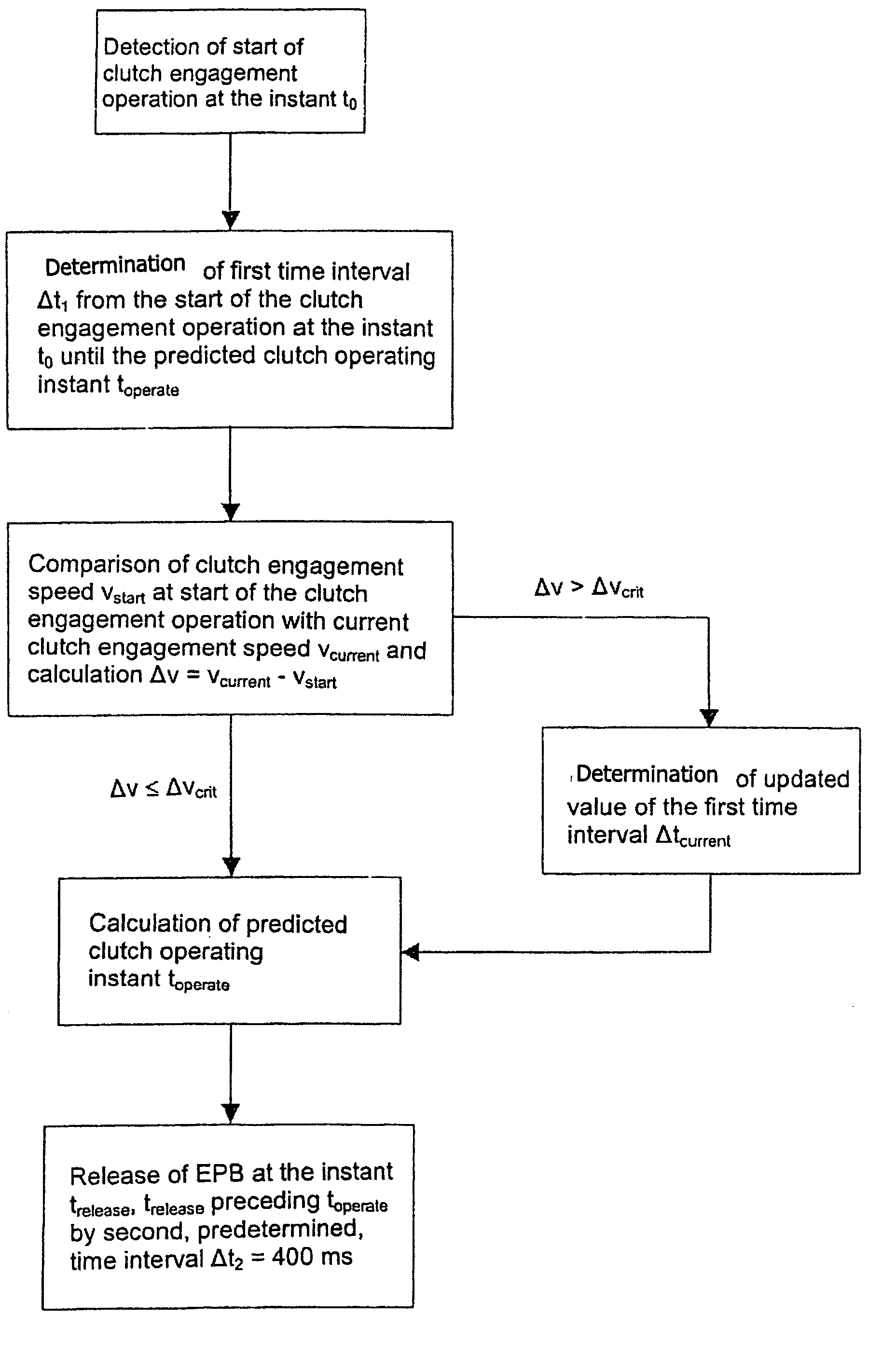
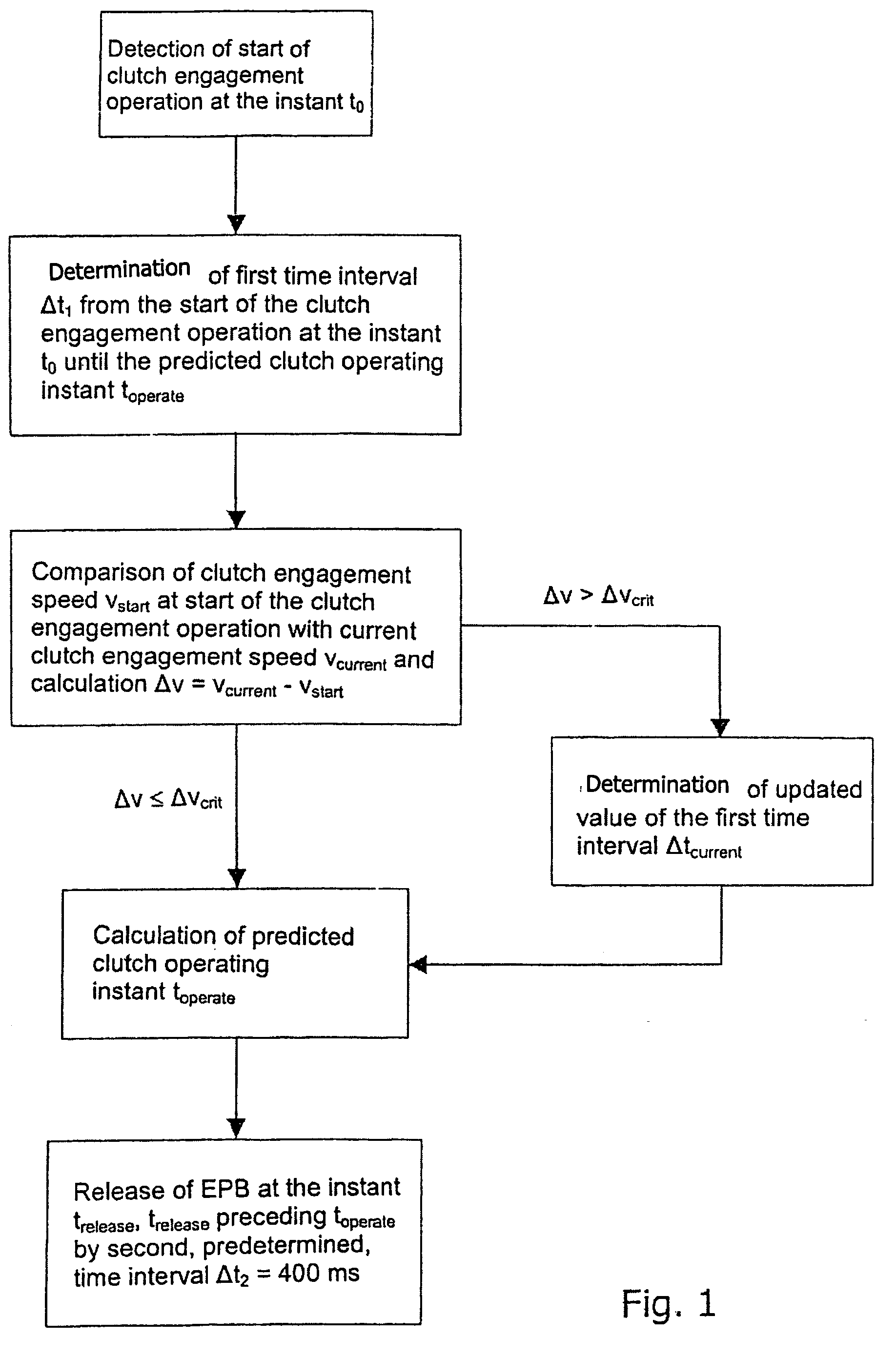
[0026] The flow diagram represented in FIG. 1 shows, in schematic form, the steps of a method for controlling a braking system equipped with an electric parking brake. In a first method step, the start of a clutch engagement operation is detected at an instant to by means of a suitable measuring device such as, for example, a clutch-travel sensor or the like. In a second method step, a first time interval Δt0 from the start of the clutch engagement operation at the instant t0 until a predicted operating instant toperate of the clutch is determined by estimation. The clutch operating instant toperate represents the moment from which a transmission of force occurs from the clutch to the driven axle of the motor vehicle, and thus enables the vehicle to move off.
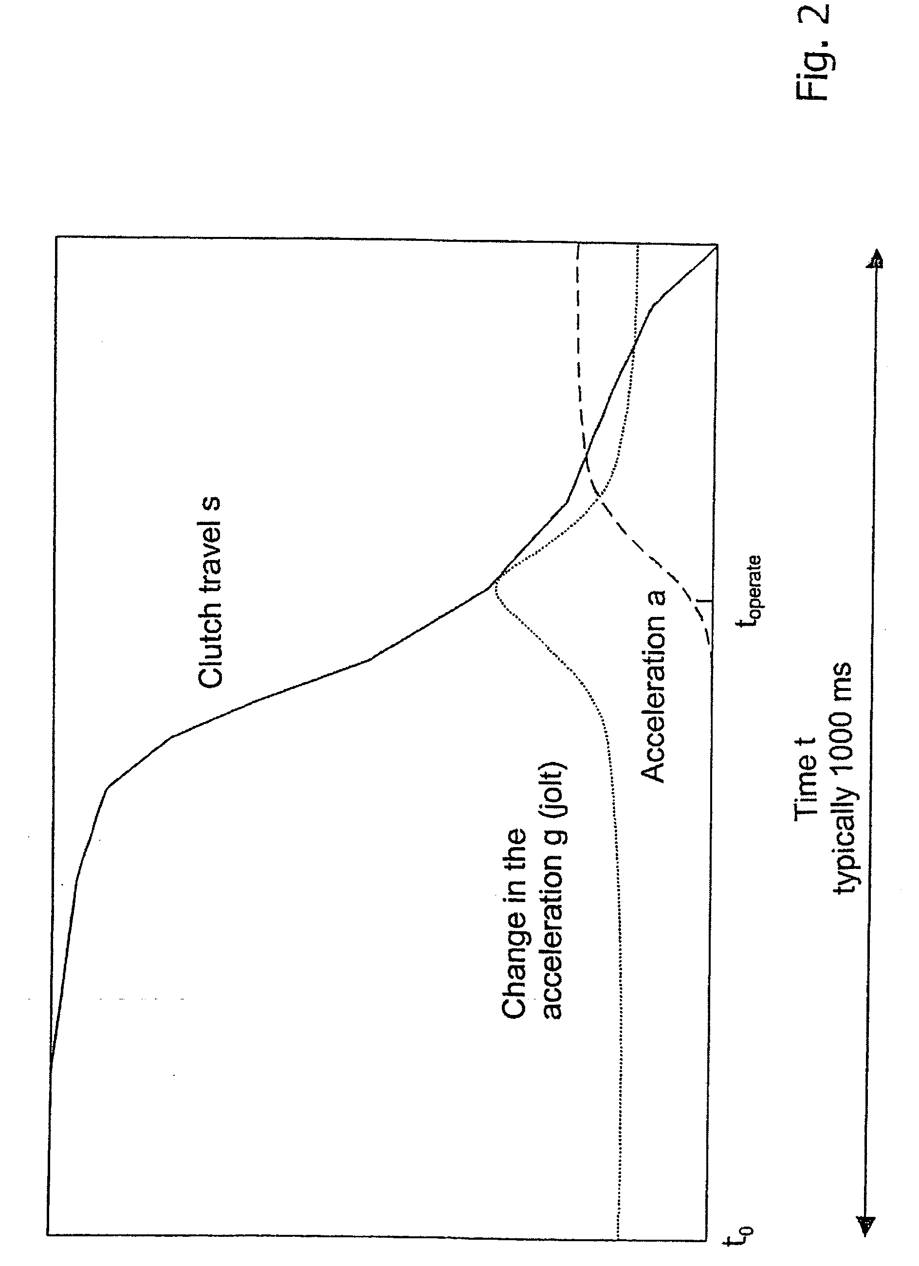
[0027] The diagram represented in FIG. 2 shows the course of the clutch travel s (unbroken line), of the acceleration a (dashed line) and of the change in the acceleration g (dotted line) of a vehicle equipped with a manual tra...
PUM
 Abstract
Description
Claims
Application Information
 - R&D
- Intellectual Property
- Life Sciences
- Materials
- Tech Scout
- Unparalleled Data Quality
- Higher Quality Content
- 60% Fewer Hallucinations
Browse by: Latest US Patents, China's latest patents, Technical Efficacy Thesaurus, Application Domain, Technology Topic, Popular Technical Reports.
© 2025 PatSnap. All rights reserved.Legal|Privacy policy|Modern Slavery Act Transparency Statement|Sitemap|About US| Contact US: help@patsnap.com


