

Coil, position indicator, position detecting device, and coil winding method
- Summary
- Abstract
- Description
- Claims
- Application Information
AI Technical Summary
Benefits of technology
Problems solved by technology
Method used
Image

Examples
first embodiment
[0031]A first embodiment of the present invention will now be described.
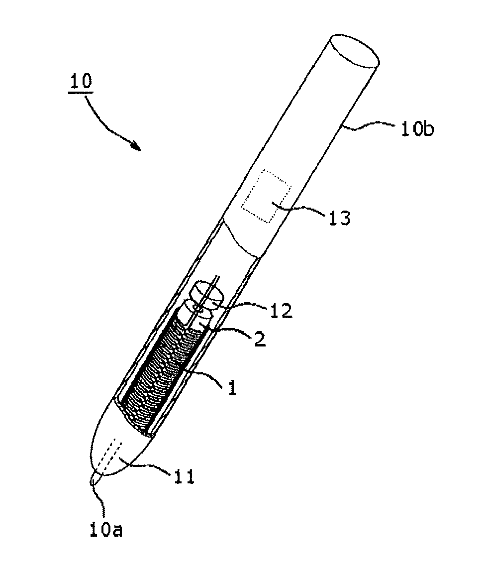
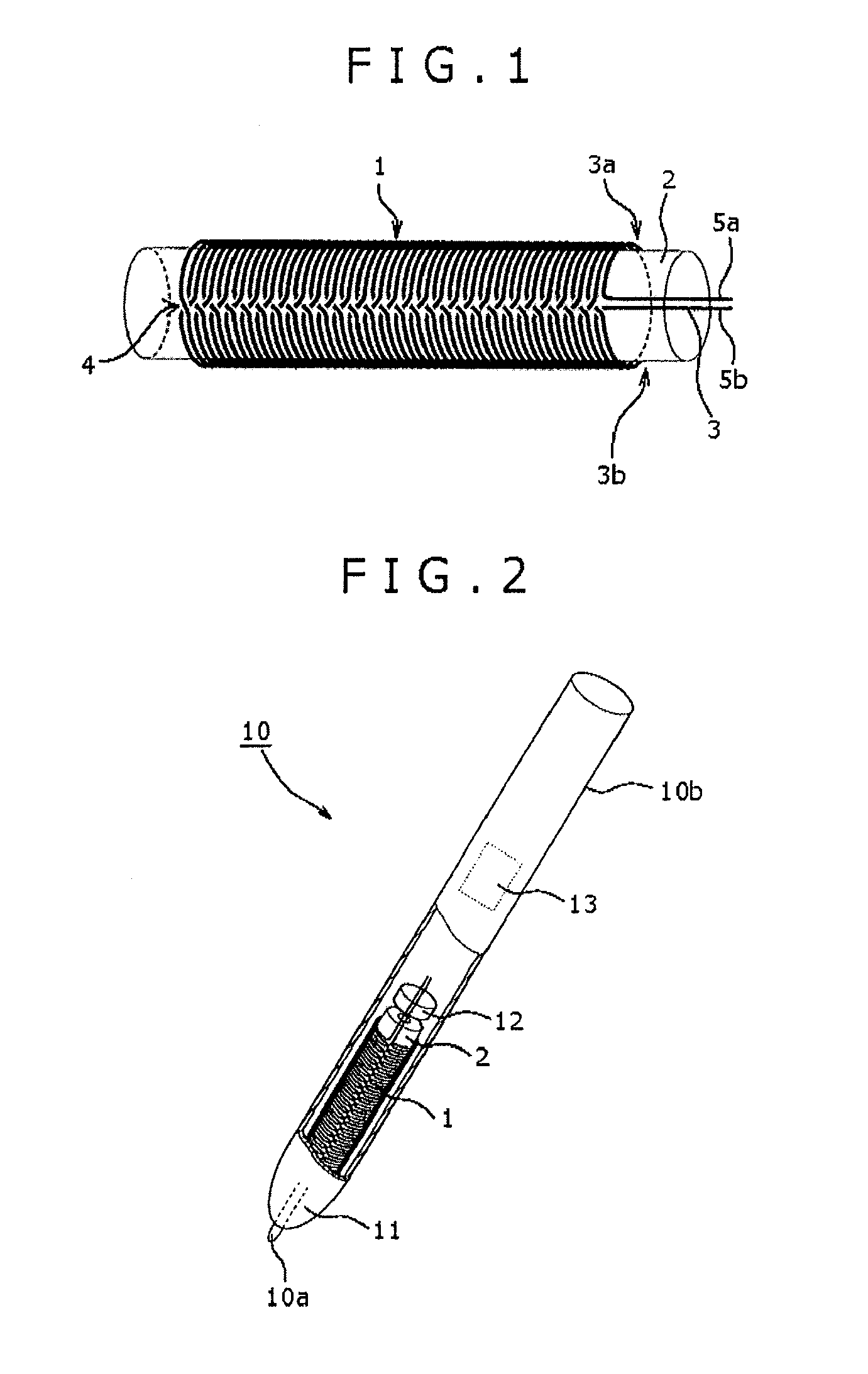
[0032]FIG. 1 shows a coil winding wire of a first embodiment of the present invention.
[0033]A conductive wire 3 that forms a coil 1 has a predetermined length. A predetermined portion of the conductive wire 3 is determined as a middle point 4, and both end portions of the conductive wire 3 with respect to the middle point 4 are designated as a first end portion 5a and a second end portion 5b, respectively. Also, a part of the conductive wire 3 extending from the middle point 4 to the first end portion 5a is designated as a first conductive wire 3a, and a part of the conductive wire 3 extending from the middle point 4 to the second end portion 5b is designated as a second conductive wire 3b.
[0034]With regard to the concept about how to wind the coil, the first conductive wire 3a is wound from its one end portion (e.g., a distal end portion) to the other end portion (e.g., a proximal end portion near the middle p...
second embodiment
[0046]A second embodiment of the present invention will now be described.
[0047]In the second embodiment of the present invention, a description will be given below with respect to the case where the present invention is applied to a coil 21 in which a middle point terminal 22 is drawn out from the middle point 4 of the conductive wire 3 wound around the ferrite core 2. In the following description, portions corresponding to those shown in FIGS. 1 to 4 described in the first embodiment are designated by the same reference numerals, respectively, and a detailed description thereof is omitted here for the sake of simplicity.
[0048]FIG. 5 is a view showing a coil winding wire of the coil 21.
[0049]The coil 21 of the second embodiment is different from the coil 1 of the first embodiment in that in the coil 21, the middle point terminal 22 is drawn out from the middle point 4 of the conductive wire 3.
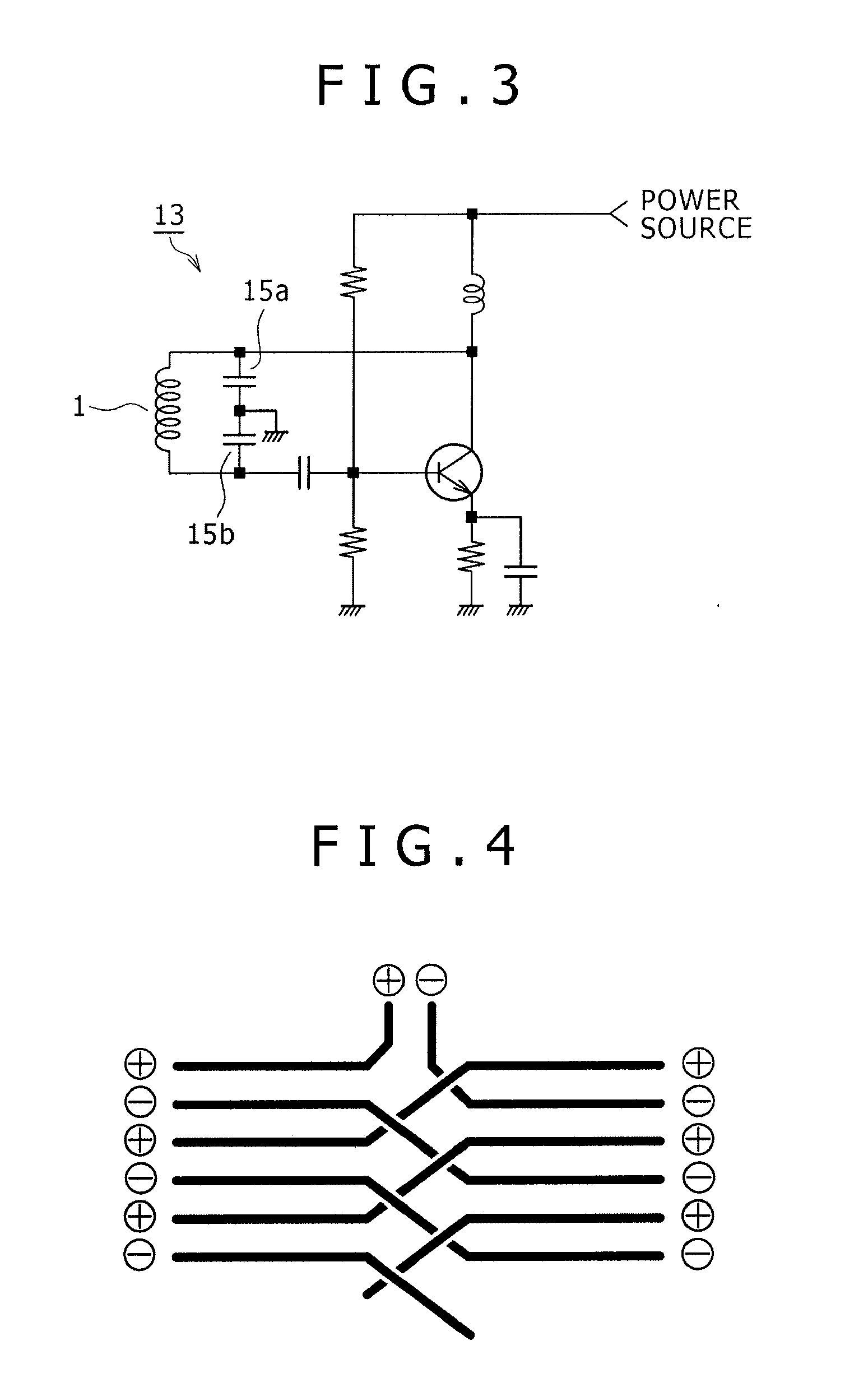
[0050]FIG. 6 is a circuit diagram of a Hartley type oscillation circuit used in the positio...
PUM
 Abstract
Description
Claims
Application Information