Antenna device and radio communication device

a radio communication and antenna device technology, applied in the direction of antennas, antenna details, antenna couplings, etc., to achieve the effect of reducing the electromagnetic wave absorption rate (sar: specific absorption rate), suppressing the effect of human body radiation pattern, and improving communication quality

Active Publication Date: 2006-06-15
FUJITSU CONNECTED TECH LTD
View PDF3 Cites 19 Cited by
  • Summary
  • Abstract
  • Description
  • Claims
  • Application Information

AI Technical Summary

Benefits of technology

[0011] In this configuration, the first case unit and the second case unit are configured to be coupled together. The antenna disposed in the first case unit is used for transmitting and receiving radio signals. The passive element disposed in the second case unit acts as an antenna due to capacitive coupling with the antenna on the first case unit side. In contrast to the radiation pattern only by the antenna, since the passive element has the antenna function, so that radiation can be obtained from the passive element and the radiation pattern thereof is transformed by overlapping with the radiation pattern of the antenna. For the radiation from the passive element, the radiation to the one side of the second case unit is suppressed by the conductor disposed in the second case unit. Therefore, the radiation from the passive element can be obtained; the antenna characteristics are improved by suppressing the radiation with the conductor; and the effects of the human body can be reduced on the radiation property.
[0022] (2) According to a radio communication device of the present invention, since equipped with the above mentioned antenna device, the electric current can be dispersed, and since the antenna properties are improved by suppressing the effects of a human body on the radiation pattern, communication quality can be improved.

Problems solved by technology

Japanese Patent Application Laid-Open Publication No. 1998-84406 does not disclose these problems nor a configuration and suggestion for resolving the problems exists.

Method used


Image

  • Antenna device and radio communication device
  • Antenna device and radio communication device
  • Antenna device and radio communication device

Examples


first embodiment

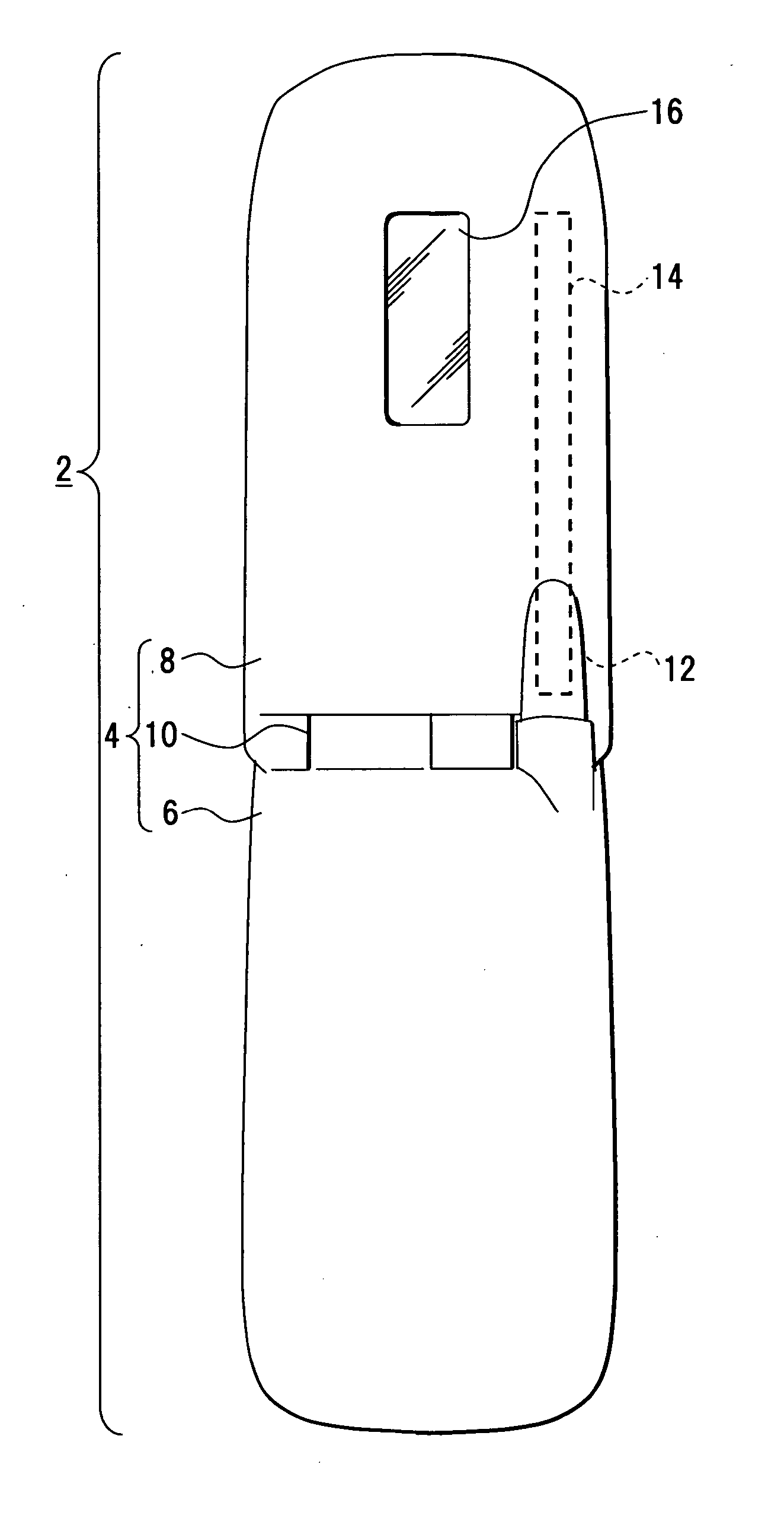
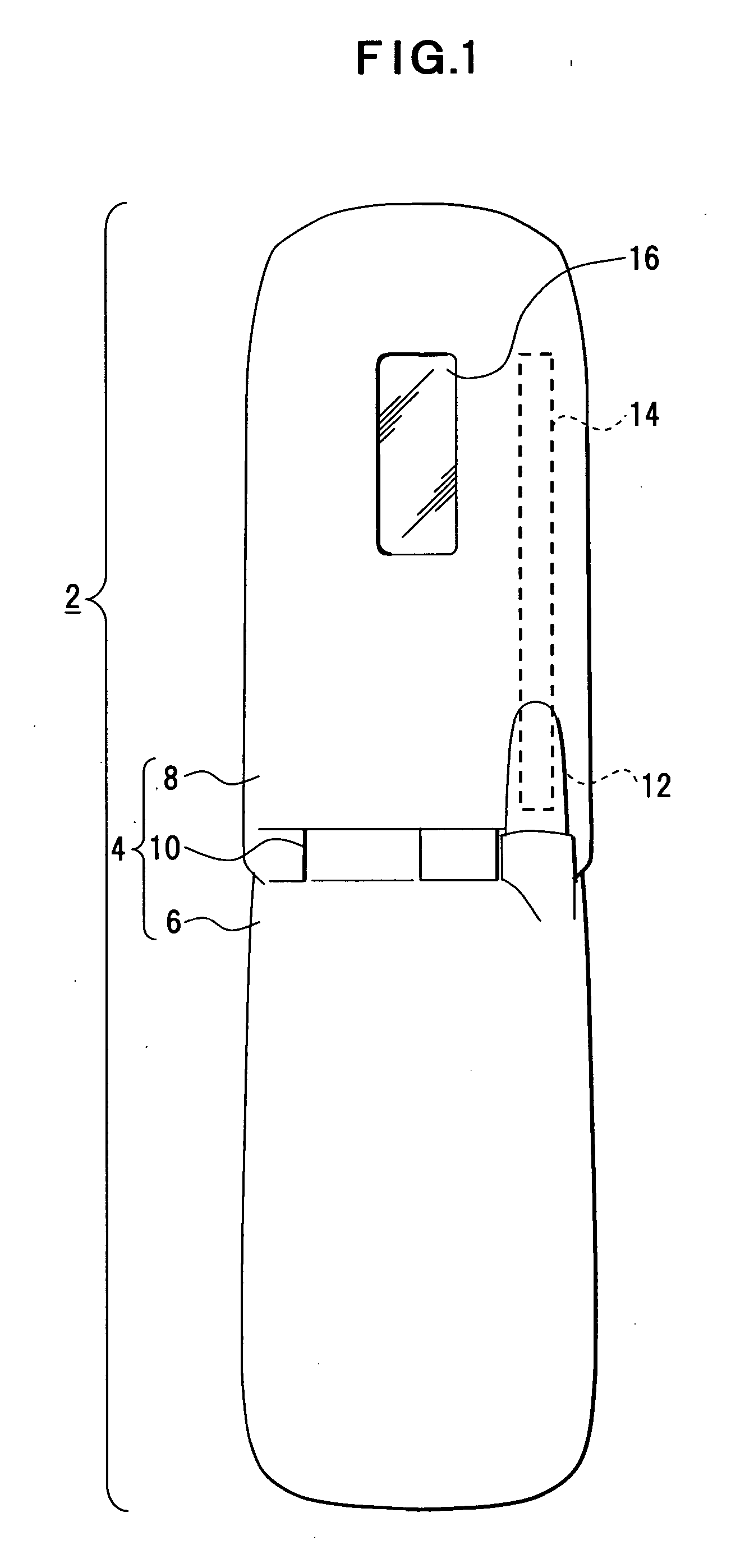
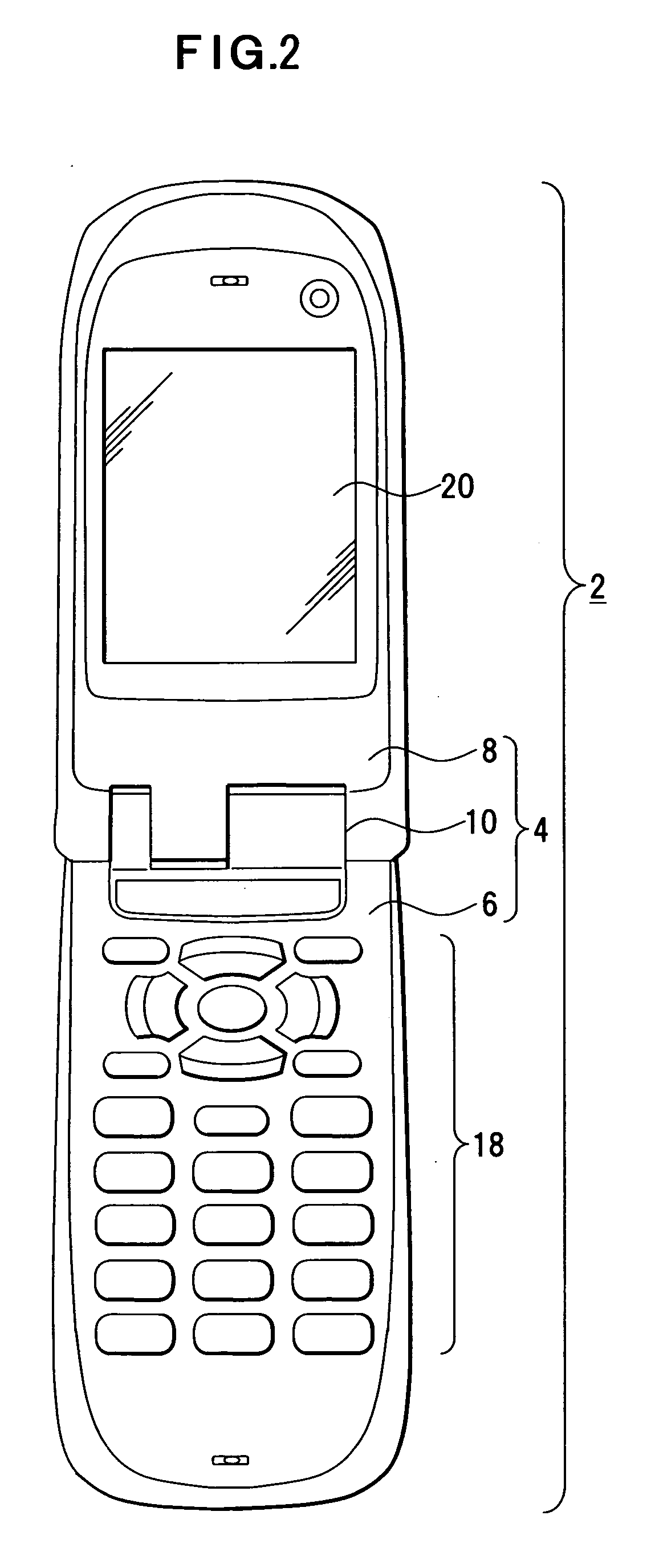
[0042] For a first embodiment of an antenna device and a radio communication device of the present invention, descriptions are made with reference to FIG. 1 and FIG. 2. FIG. 1 shows a cellular phone opened and viewed from the backside, and FIG. 2 shows the cellular phone opened and viewed from the front side.

[0043] As an example of a radio communication device, the cellular phone 2 is provided with a case 4 having folding structure, and this case 4 is configured to be foldable at a hinge unit 10 by coupling a first case unit 6 with a second case unit 8 via the hinge unit 10. The case units 6 and 8 are made of insulating synthetic resin, for example. In this case, if the case unit 6 is a fixed portion, the case unit 8 becomes a moving portion, and if the case unit 8 is a fixed portion, the case unit 6 becomes a moving portion.

[0044] The case unit 6 is provided with an antenna 12, and a leading end of this antenna 12 protrudes to the side of the case unit 8 such that the leading end...

second embodiment

[0068] For a second embodiment of an antenna device and a radio communication device of the present invention, descriptions are made with reference to FIG. 13, FIG. 14 and FIG. 15. FIG. 13 shows a cellular phone having a case with turning structure in the middle of turning; FIG. 14 shows an internal structure before turning; and FIG. 15 shows an internal structure after turning. The cellular phone shown in FIG. 13 to FIG. 15, the same symbols are added to the same portions as the first embodiment.

[0069] The cellular phone 2 according to this embodiment is comprised of a case 4 with turning structure, and this case 4 is comprised of a first case unit 6 and a second case unit 8 and formed by coupling the case unit 6 and the case unit 8 via a supporting axis 11 to be pivotable. As shown by arrows A and B of FIG. 13, for example, by rotating the case unit 8 within the angular range of 180 degrees from a state that the case unit 8 is overlapped with the case unit 6, the case unit 8 is e...

third embodiment

[0071] For a third embodiment of an antenna device and a radio communication device of the present invention, descriptions are made with reference to FIG. 16, FIG. 17 and FIG. 18. FIG. 16 shows a cellular phone having a case with sliding structure in the middle of sliding; FIG. 17 shows an internal structure before sliding; and FIG. 18 shows an internal structure after sliding. The cellular phone shown in FIG. 16 to FIG. 18, the same symbols are added to the same portions as the first embodiment.

[0072] The cellular phone 2 according to this embodiment is comprised of a case 4 with sliding structure, and this case 4 is formed by coupling the case unit 6 and the case unit 8 via a slide supporting portion 13 to be able to slide. As shown by arrows C and D of FIG. 16, by sliding the case unit 8 on the case unit 6 from a state that the case unit 8 overlaps with the case unit 6 as shown by a chain double-dashed line, the case unit 8 is extended from the case unit 6, and this is the same ...


PUM


Abstract

The present invention relates to an antenna device disposed in a case and prevents antenna characteristics from being degraded by a human body. The antenna device is configured such that it comprises an antenna that is disposed in a first case unit, a passive element that is disposed in a second case unit coupled to the first case unit and that can obtain an antenna function due to capacitive coupling with the antenna, and a conductor (printed board) that is disposed in the second case unit to suppress radiations from the passive element to one side of the second case unit.

Description

BACKGROUND OF THE INVENTION [0001] 1. Field of the Invention [0002] The present invention relates to an antenna device used in various radio communication devices such as a cellular phone having a case with folding structure, turning structure, sliding structure or the like and, for example, to an antenna device and a radio communication device of which radiation patterns can be switched by an opening or closing operation of the case unit. [0003] 2. Description of the Related Art [0004] For an antenna used in various radio communication devices such as a cellular phone, radiation efficiency is used to evaluate a property of the antenna. Since the radiation efficiency varies by a distance between the antenna and a ground conductor, a matching circuit or the like, improvement in the antenna characteristics is relatively easy by adjusting the radiation efficiency, however, for the radio communication device used in close proximity to a human body, it is known that the radiation pattern...

Claims


Application Information

Patent Timeline
Patent Type & Authority Applications(United States)
IPC IPC(8): H01Q1/24
CPCH01Q1/243H01Q1/52
Inventor KANAZAWA, MASARU
Owner FUJITSU CONNECTED TECH LTD
Why Eureka
Try Eureka