Array antenna

Inactive Publication Date: 2019-02-28
TOYOTA JIDOSHA KK
View PDF9 Cites 1 Cited by
  • Summary
  • Abstract
  • Description
  • Claims
  • Application Information

AI Technical Summary

Benefits of technology

The patent aims to provide an array antenna that can prevent radio waves from bouncing back and causing interference. The technical effect of the patent is to improve the performance of the array antenna and reduce interference.

Problems solved by technology

This increases erroneous detection and noise, resulting in a reduction in a detection performance of the array antenna.

Method used


Image

  • Array antenna
  • Array antenna
  • Array antenna

Examples


first modified example

[0043]A first modified example of the array antenna according to the embodiment described above will be explained with reference to FIG. 7. FIG. 7 is an enlarged view illustrating a reflection end of an array antenna according to the first modified example of the embodiment.

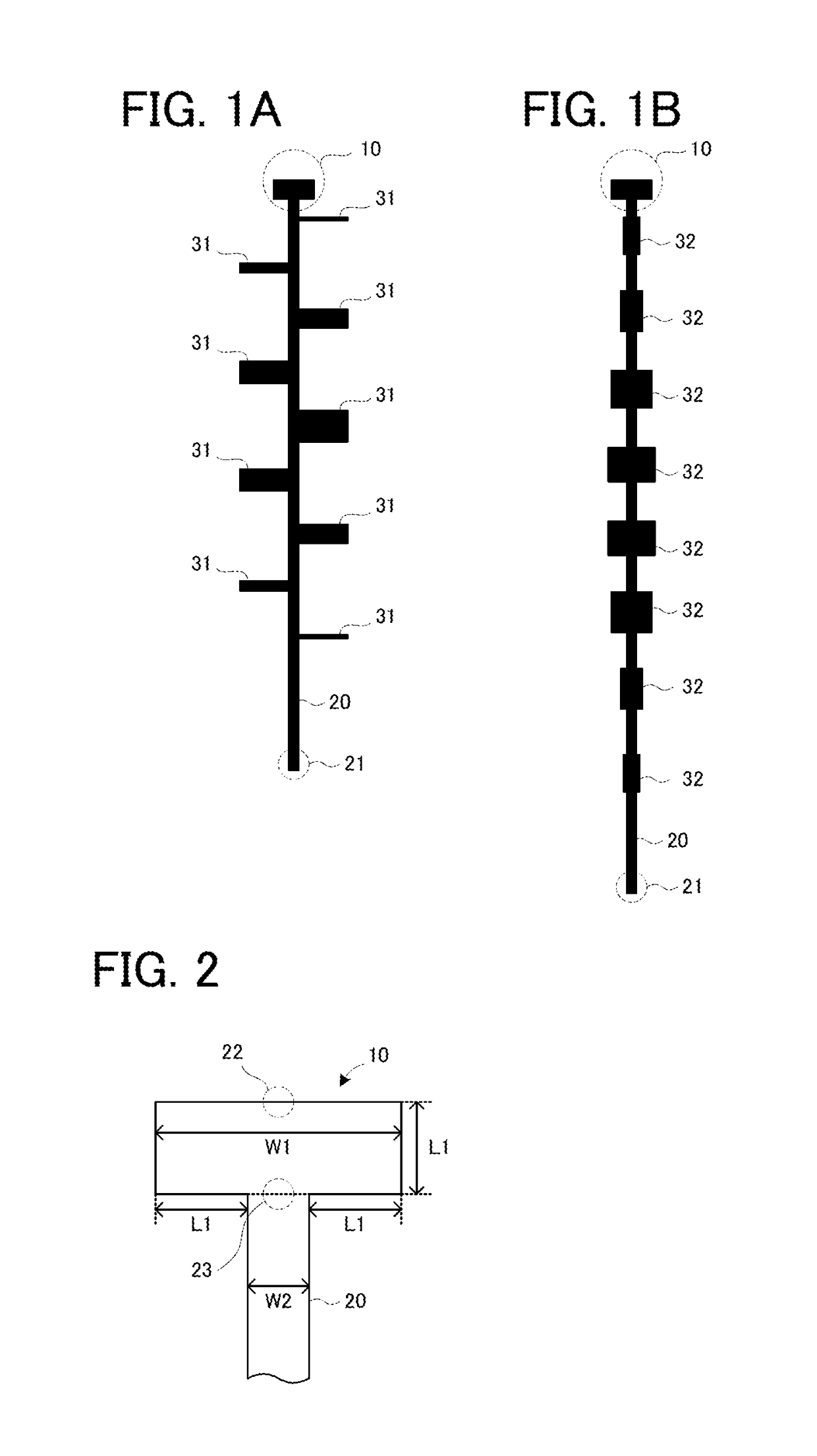
[0044]The part 10 may include, as illustrated in FIG. 7, a first part 11 with the width W2 and a second part 12 (e.g., a patch) arranged to sandwich the first part 11 therebetween. In an example illustrated in FIG. 7, the second part 12 is a square with a side of a1 (=L1).

second modified example

[0045]A second modified example of the array antenna according to the embodiment described above will be explained with reference to FIG. 8. FIG. 8 is an enlarged view illustrating a reflection end of an array antenna according to the second modified example of the embodiment.

[0046]The part 10 according to the embodiment may be formed to partially have a circular arc outer edge, as is a part 10′ illustrated in FIG. 8. An electric current propagated or flowing through the feeding line 20 concentrates on a side end of the feeding line 20. The electric current flowing on the side end radially spreads in a part in the vicinity of the reflection end, which is the part 10′ here. A shape of the part 10′ reflects a current distribution radially spreading in the part 10′.

[0047]In the part 10′, a radius (i.e., a2) of a part projecting to the left of the part 10′ from a left edge of the feeding line 20 is desirably a radius corresponding to λ / 4 in electrical length as the part 10′ is viewed fr...

third modified example

[0048]A third modified example of the array antenna according to the embodiment described above will be explained with reference to FIG. 9. FIG. 9 is an enlarged view illustrating a reflection end of an array antenna according to the third modified example of the embodiment.

[0049]In the part 10 according to the embodiment described above, as in a part 10″ illustrated in FIG. 9, a length (i.e., a3) in the direction of the feeding line 20 extending may be a length corresponding to 3λ / 4 in electrical length as the part 10″ is viewed from the connector. In this case, the path difference between the electric power reflected on the reflection end 22 (refer to FIG. 2) and the electric power reflected on the connector 23 (refer to FIG. 2) is two-third times as long as the wavelength, i.e., “3λ / 2”, in electrical length. Thus, the electric power reflected on the reflection end 22 and the electric power reflected on the connector 23 are in-phase and intensify each other. Therefore, according t...


PUM


Abstract

An array antenna is provided with: a feeding line; and a plurality of radiating elements, wherein the feeding line has a part whose length corresponds to (2n−1) / 4 (wherein n is a natural number) times as long as a wavelength, in electrical length, from a reflection end of said feeding line, wherein the part is wider than another part that is on an input end side with respect to the part.

Description

CROSS-REFERENCE TO RELATED APPLICATIONS[0001]This application is based upon and claims the benefit of priority of the prior Japanese Patent Application No. 2017-167169, filed on Aug. 31, 2017, the entire contents of which are incorporated herein by reference.BACKGROUND1. Technical Field[0002]Embodiments of the present disclosure relate to an array antenna.2. Description of the Related Art[0003]For this type of antenna, for example, there is proposed a planar array antenna having a feeding strip line, which linearly extends, and 10 radiating antenna elements, which project perpendicularly from the line (refer to Japanese Patent Application Laid Open No. 2001-111330 (Patent Literature 1)).[0004]The array antenna in a shape similar to that of the feeding strip line disclosed in the Patent Literature 1 has relatively large radio wave radiation or emission from a reflection end. The radio wave radiation from the reflection end is unnecessary radio wave radiation coming from a part other ...

Claims


Application Information

Patent Timeline
IPC IPC(8): H01Q21/06H01Q13/08H01Q21/00
CPCH01Q21/06H01Q13/08H01Q21/0075H01Q1/36H01Q21/00H01Q13/206H01Q21/08H01Q21/22
Inventor MINAMI, YOSHIAKI
Owner TOYOTA JIDOSHA KK
Why Eureka
Try Eureka