Liquid ejecting apparatus and method for adjusting positions of nozzle rows

a technology of liquid ejecting apparatus and nozzle rows, which is applied in the direction of power drive mechanisms, coatings, printing, etc., can solve the problems of lack of coordination, inability to obtain attractive print images, and inability to print attractive images on print paper, so as to accurately coordinate the nozzle rows with one

Inactive Publication Date: 2009-09-22
SEIKO EPSON CORP
View PDF15 Cites 10 Cited by
  • Summary
  • Abstract
  • Description
  • Claims
  • Application Information

AI Technical Summary

Benefits of technology

[0009]The present invention has been made in view of the foregoing issues, and it is an object thereof to achieve a liquid ejecting apparatus in which it is possible to accurately coordinate the nozzle rows with one another, as regards the positions where liquid that has been ejected onto a medium lands, and also a method for adjusting the positions of those nozzle rows.

Problems solved by technology

Therefore, if the positions where dot rows are formed, which are the positions where the ink droplets land on the print paper, deviate from expected design positions, then an attractive print image cannot be printed on the print paper.
In particular, in the case of a large-size inkjet printer provided with a plurality of print heads as described above, if the positions of the nozzle rows are not consistent among the plurality of print heads on the carriage, then there will be a lack of coordination in the positions where the dot rows are formed among the print heads, and if all of the print heads are used to draw a single print image, then an attractive print image cannot be obtained.
Thus, if the print head that is taken as the reference is prone to vibration during carriage movement, the positions where dot rows are formed by the reference print head will fluctuate, and it is difficult to coordinate the dot-row formation positions among the print heads even if the positions of the other print heads are precisely adjusted with respect to the reference.
As a result, an attractive print image cannot be obtained.

Method used


Image

  • Liquid ejecting apparatus and method for adjusting positions of nozzle rows
  • Liquid ejecting apparatus and method for adjusting positions of nozzle rows
  • Liquid ejecting apparatus and method for adjusting positions of nozzle rows

Examples


Embodiment Construction

[0032]At least the following matters will be made clear by the detailed explanation of the invention in the present specification.

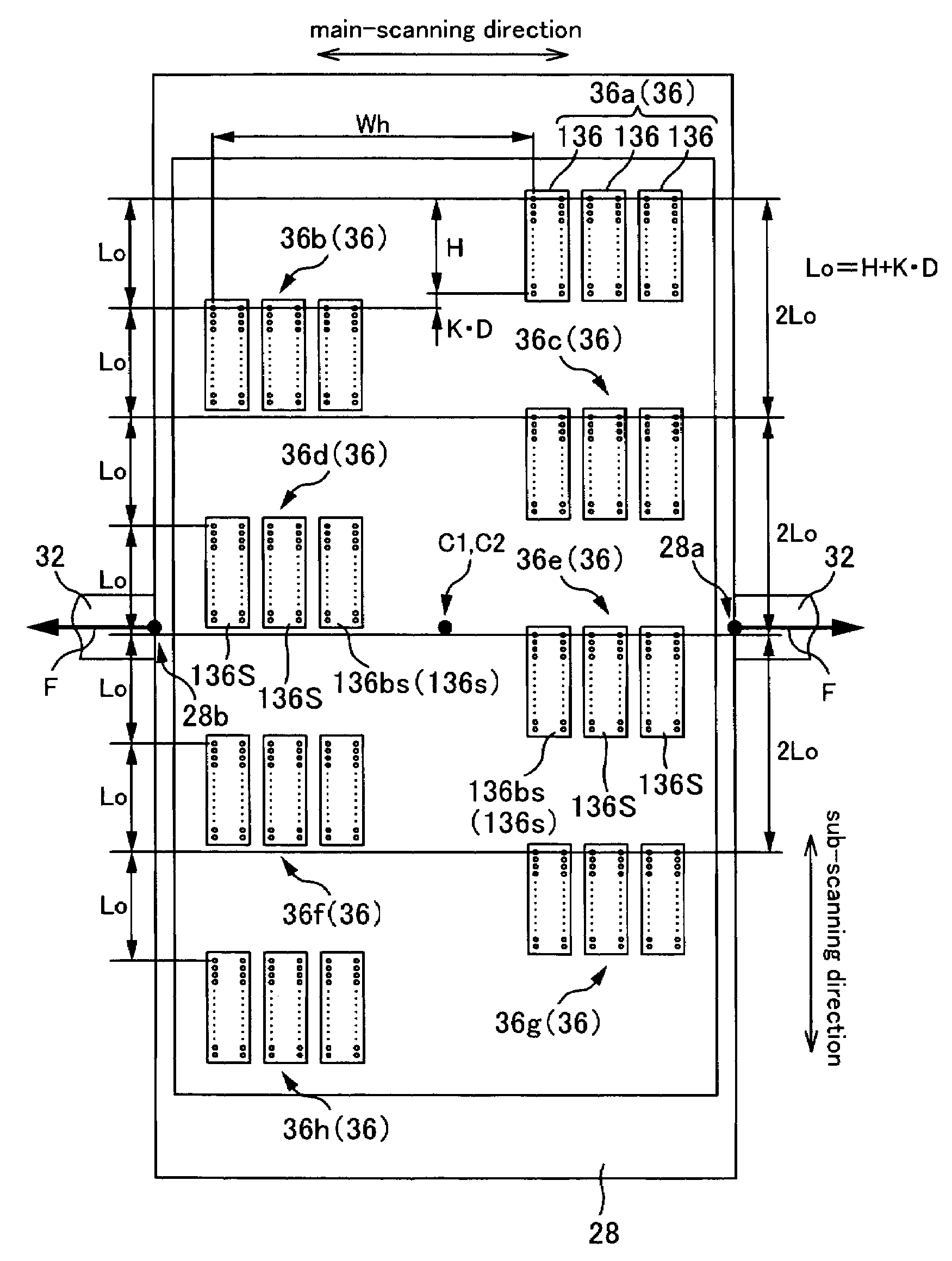
[0033]An aspect of the present invention is liquid ejecting apparatus comprising: a moving unit that moves by receiving a moving force; and a plurality of nozzle rows for ejecting liquid onto a medium, wherein each of the nozzle rows is adjusted in its position on the moving unit, taking a nozzle row that is arranged on a side close to a line of action of the moving force as a reference.

[0034]With such a liquid ejecting apparatus, the positions of the nozzle rows are adjusted taking a nozzle row on the side close to the line of action of the moving force as a reference. This is because the closer a section is to the line of action on the moving unit, the smaller its vibration during movement due to the direct transmission of the moving force. That is, the closer the nozzle row is to the line of action, the smaller the discrepancy due to vibration is in th...


PUM


Abstract

A liquid ejecting apparatus comprises a moving unit that moves by receiving a moving force, and a plurality of nozzle rows for ejecting liquid onto a medium, wherein each of the nozzle rows is adjusted in its position on the moving unit, taking a nozzle row that is arranged on a side close to a line of action of the moving force as a reference.

Description

CROSS-REFERENCE TO RELATED APPLICATIONS[0001]The present application claims priority upon Japanese Patent Application No. 2003-29720 filed on Feb. 6, 2003, which is herein incorporated by reference.BACKGROUND OF THE INVENTION[0002]1. Field of the Invention[0003]The present invention relates to liquid ejecting apparatuses provided with a moving unit that moves when it receives a moving force, and a plurality of nozzle rows for ejecting liquid onto a medium, and with which it is possible to adjust the positions of the nozzle rows on the moving unit, and methods for adjusting the positions of those nozzle rows.[0004]2. Description of the Related Art[0005]In recent years, inkjet printers that eject ink as a liquid have become particularly popular as liquid ejecting apparatuses for ejecting liquid from nozzle rows (made of numerous nozzles arranged in lines) onto a medium. These inkjet printers are provided with a print head provided with a plurality of nozzle rows, and a carriage that i...

Claims


Application Information

Patent Timeline
Patent Type & Authority Patents(United States)
IPC IPC(8): B41J29/393B41J2/015B41J23/00B41J2/01B05C5/00B05C11/10B05D1/26B41J2/045B41J2/055B41J2/15B41J2/21
CPCB41J2/15B41J2/2135B41J25/304B41J25/005B41J2202/20
Inventor MITSUZAWA, TOYOHIKO
Owner SEIKO EPSON CORP
Why Eureka
Try Eureka