Method and system for controlling a braking system equipped with an electric parking brake

a technology of electric parking brake and braking system, which is applied in the direction of brake action initiation, braking system, mechanical apparatus, etc., can solve the problems of electric parking brake, inability to fully release with sufficient speed to permit unimpeded moving off of the vehicle, and unpleasant jolt on the rear axle of the vehicl

Active Publication Date: 2008-08-05
LUCAS AUTOMOTIVE GMBH
View PDF8 Cites 14 Cited by
  • Summary
  • Abstract
  • Description
  • Claims
  • Application Information

AI Technical Summary

Benefits of technology

[0005]The invention is based on the object of providing a method and a system for controlling a braking system equipped with an electric parking brake, which method and system render possible jolt-free moving-off that is comfortable for the driver, even in the case of fast moving-off operations of a vehicle equipped with a manual transmission.
[0006]This object is achieved by a control method having the features stated in the appended claim 1, and by a control system having the features stated in the appended claim 10. In the case of this method and system, the electric parking brake is released in response to the identification of a moving-off operation, wherein, according to the invention, a release instant of the electric parking brake is defined in dependence on at least one measured parameter of a clutch engagement operation. In comparison with a method and system in which, for example, the electric parking brake is released solely in dependence on the actuation of the accelerator by a driver, the method and system according to the invention permit a more precise coordination of the deactivation of the electric parking brake with the clutch engagement operation, and thus with the moving-off operation of the vehicle, particularly in the case of a vehicle equipped with a manual transmission.
[0007]In the case of the method and system according to the invention, the clutch engagement operation is expediently monitored by means of suitable measuring devices. For example, the start of the clutch engagement operation, or further parameters which characterize the course of the clutch engagement operation, such as the clutch engagement speed, may be detected by means of suitable sensors and the release instant of the EPB then defined in response to the parameter or parameters of the clutch engagement operation detected by the sensors. In this case, the response time of the EPB, i.e. the time required for complete removal of the braking forces applied by the EPB, may also be taken into account in the definition of an appropriate release instant of the electric parking brake. The appropriate selection of the release instant of the EPB in dependence on the detected parameters of the clutch engagement operation renders possible a jolt-free moving-off of the vehicle that is comfortable for the driver.

Problems solved by technology

In the case of the automatic release of the electric parking brake in response to the identification of a moving-off operation, however, there is the problem, particularly in the case of fast moving-off operations of a vehicle equipped with a manual transmission, that the electric parking brake, owing to its response time from the start of its deactivation to the complete removal of the braking forces, cannot be fully released with sufficient speed to permit unimpeded moving-off of the vehicle.
Owing to the braking forces, applied by the EPB, which have not yet been fully removed at this instant, there is an unpleasant jolt on the rear axle of the vehicle which is perceptible by the driver upon moving-off of the vehicle.

Method used


Image

  • Method and system for controlling a braking system equipped with an electric parking brake
  • Method and system for controlling a braking system equipped with an electric parking brake
  • Method and system for controlling a braking system equipped with an electric parking brake

Examples


Embodiment Construction

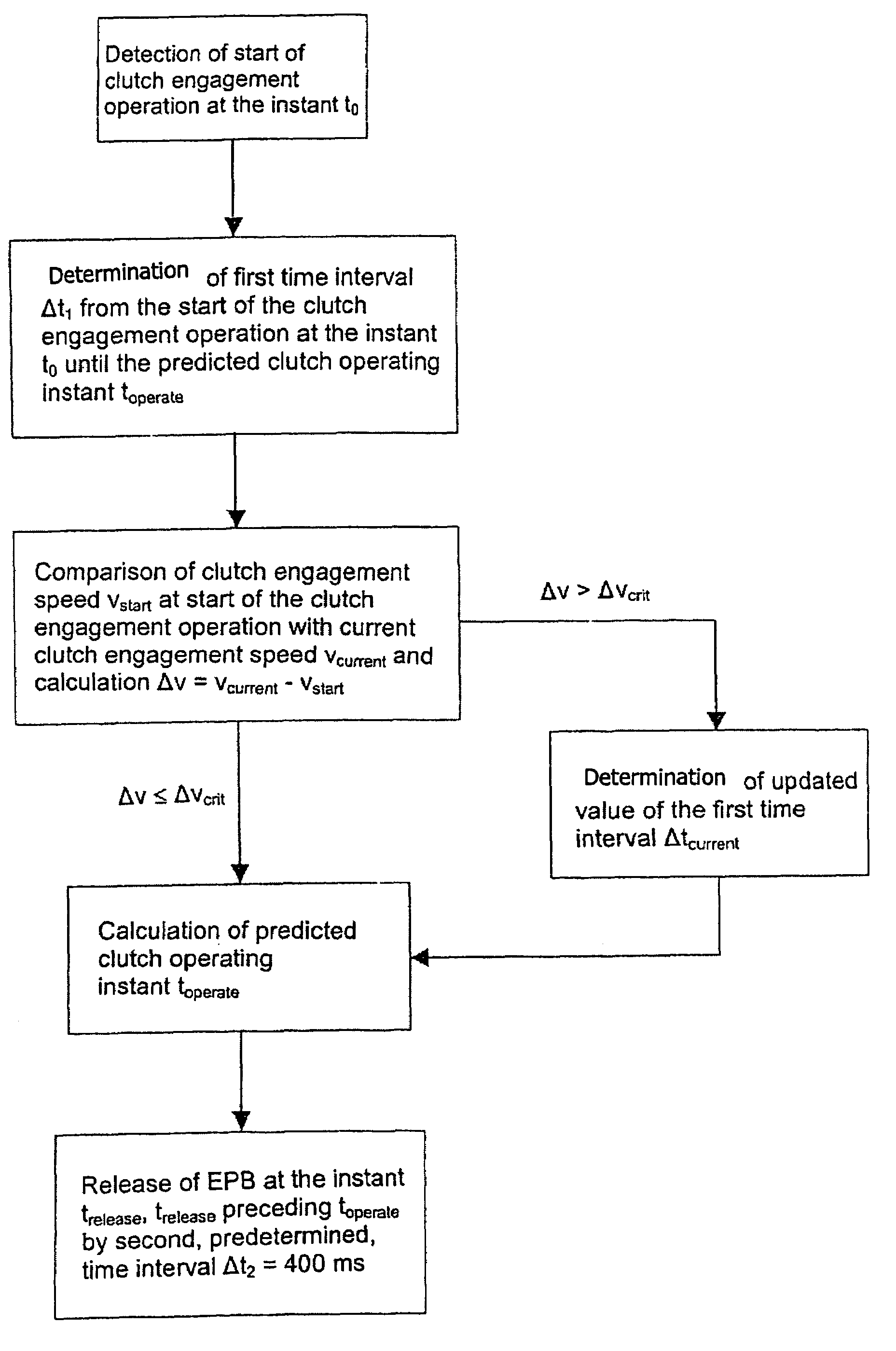
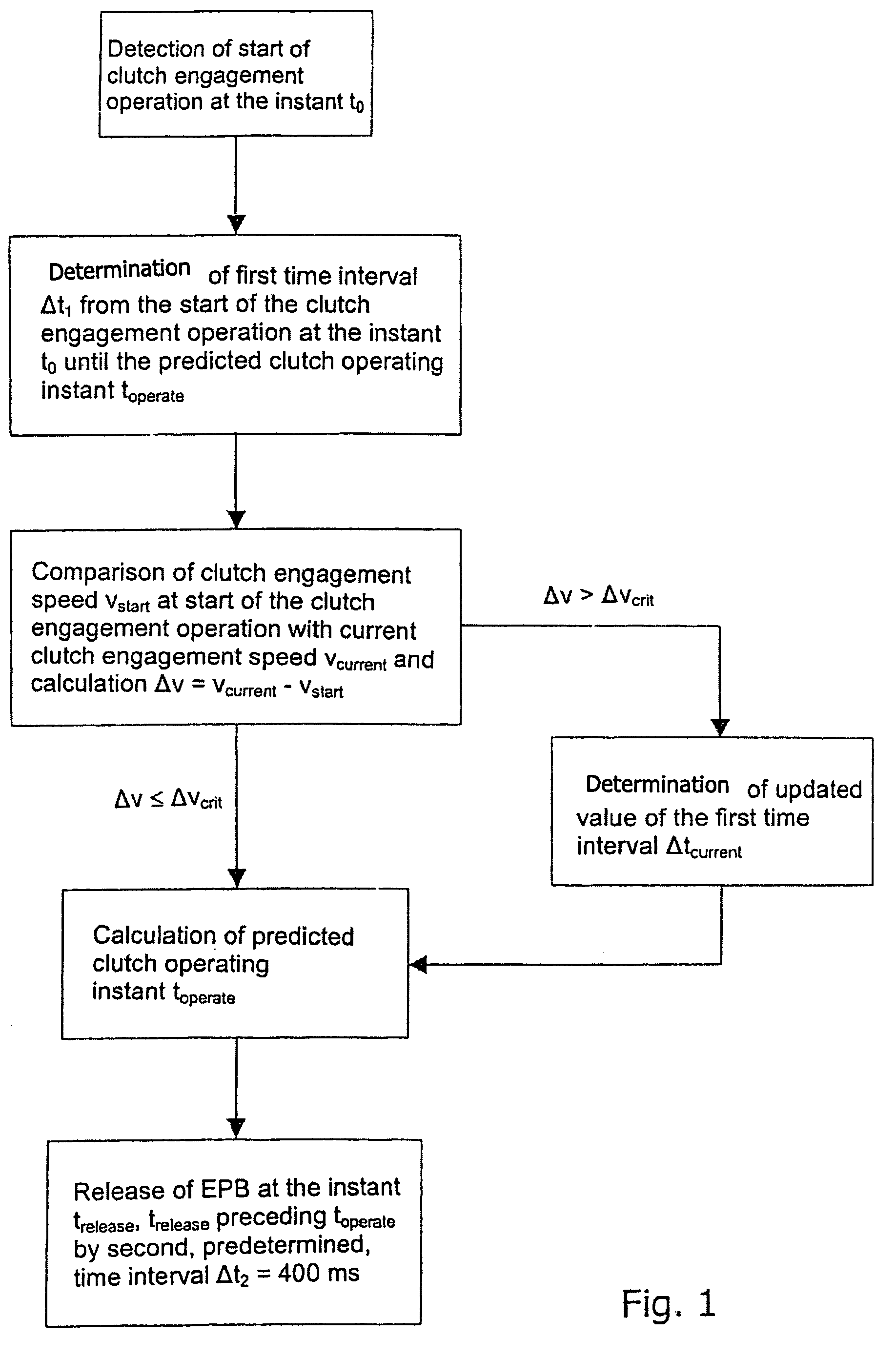
[0026]The flow diagram represented in FIG. 1 shows, in schematic form, the steps of a method for controlling a braking system equipped with an electric parking brake. In a first method step, the start of a clutch engagement operation is detected at an instant t0 by means of a suitable measuring device such as, for example, a clutch-travel sensor or the like. In a second method step, a first time interval Δt1 from the start of the clutch engagement operation at the instant t0 until a predicted operating instant toperate of the clutch is determined by estimation. The clutch operating instant toperate represents the moment from which a transmission of force occurs from the clutch to the driven axle of the motor vehicle, and thus enables the vehicle to move off.

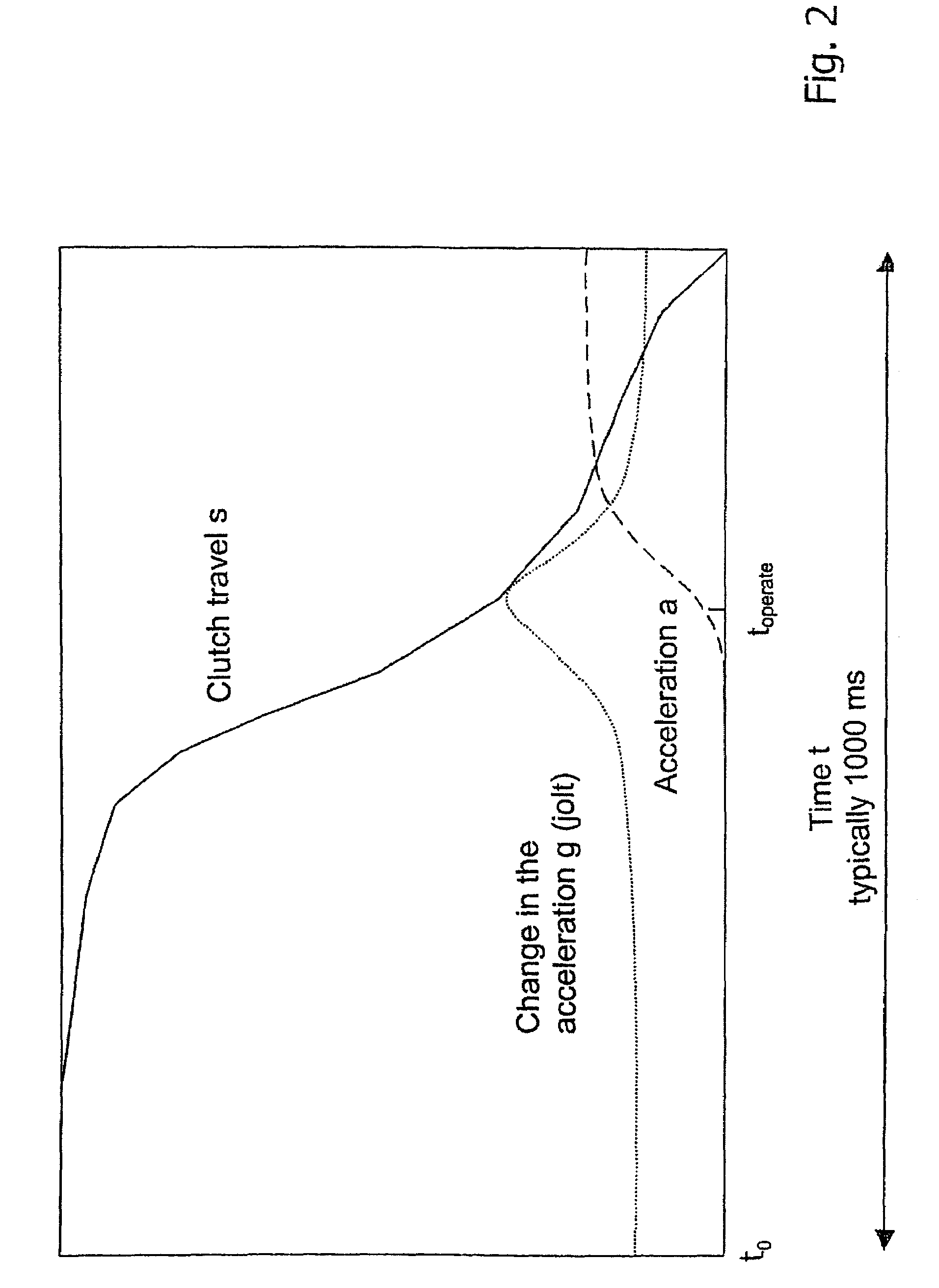
[0027]The diagram represented in FIG. 2 shows the course of the clutch travel s (unbroken line), of the acceleration a (dashed line) and of the change in the acceleration g (dotted line) of a vehicle equipped with a manual transm...


PUM


Abstract

In a method and system for controlling a braking system, equipped with an electric parking brake, for a motor vehicle, the electric parking brake is released in response to an identification of a moving-off operation. A release instant of the electric parking brake is defined in dependence on at least one measured parameter of a clutch engagement operation. In comparison with a method and system in which, for example, the electric parking brake is released in dependence on the actuation of the accelerator by a driver, the method and system permit a more precise coordination of the deactivation of the electric parking brake with the clutch engagement operation, and thus with the moving-off operation of the vehicle, particularly in the case of a vehicle equipped with a manual transmission.

Description

CROSS-REFERENCE TO RELATED APPLICATIONS[0001]This application is a continuation of International Application No. PCT / EP2004 / 005361 filed May 18, 2004, the disclosures of which are incorporated herein by reference, and which claimed priority to German Patent Application No. 103 24 446.8 filed May 28, 2003, the disclosures of which are incorporated herein by reference.BACKGROUND OF THE INVENTION[0002]The invention relates to a method and a system for controlling a braking system, equipped with an electric parking brake (EPB), for a motor vehicle.[0003]Known in the art, for the purpose of improving driving comfort, is the practice of controlling modern braking systems, that are equipped with an electric parking brake, in such a way that automatic activation and deactivation of the electric parking brake is possible in addition to manual actuation. The EPB is automatically activated, for example, as soon as the vehicle is stationary, and is automatically released again as soon as a movi...

Claims


Application Information

Patent Timeline
Patent Type & Authority Patents(United States)
IPC IPC(8): B60W10/00B60W10/02B60W10/04B60W10/18B60T7/10B60T13/74
CPCB60T7/107B60T13/74Y10T477/80Y10T477/74Y10T477/75
Inventor KINDER, RALF
Owner LUCAS AUTOMOTIVE GMBH
Why Eureka
Try Eureka