Sub-assembly for an electromechanical brake actuator

a brake actuator and sub-assembly technology, applied in the direction of differential gearings, belts/chains/gearings, toothed gearings, etc., can solve the problems of increasing wear potential affecting the service life of the brake actuator, and intensifying the wear of the gearing

Active Publication Date: 2015-09-29
LUCAS AUTOMOTIVE GMBH +1
View PDF19 Cites 19 Cited by
  • Summary
  • Abstract
  • Description
  • Claims
  • Application Information

AI Technical Summary

Benefits of technology

[0012]The output-side gearwheel of the second gearing stage may have been connected to rotate with a sun gear of the third gearing stage taking the form of a planetary gearing. The sun gear may have been arranged concentrically with the output-side gearwheel of the second gearing stage. As an alternative to this, the sun gear may have been integrally formed with the output-side gearwheel of the second gearing stage. The advantage of an integral design lies in a lessening of gearing components, by virtue of which the mounting is facilitated and the service life of the subassembly is increased.
[0021]The brake actuator may further include a holding element that has been provided for supporting the planet carrier, with the planet gears resting thereon, rotatably in the ring gear. The holding element may have been formed as a simple ring which is capable of being fastened to the underside of the ring gear in exactly fitting manner. In this way, the planet carrier can be prevented from falling out of the ring gear.

Problems solved by technology

With increasing complexity of the gearing, however, the wear potential of the brake actuator rises, by virtue of which, in turn, the service life of the brake actuator is impaired.
For example, an inadequate support of greatly loaded gearing components may intensify the wear in the gearing, by virtue of which the service life and the efficiency of the brake actuator decline.

Method used


Image

  • Sub-assembly for an electromechanical brake actuator
  • Sub-assembly for an electromechanical brake actuator
  • Sub-assembly for an electromechanical brake actuator

Examples


Embodiment Construction

[0030]In the following an embodiment of a subassembly of an electromechanical brake actuator for an electrically operated parking brake will be elucidated. Matching elements in the Figures have been denoted by the same reference symbols. Statements such as ‘upper side’ and ‘underside’ refer to the orientation, shown in the Figures, of the assembly. It will be understood that the subassembly has been incorporated—as a rule, horizontally—within an electric parking brake.

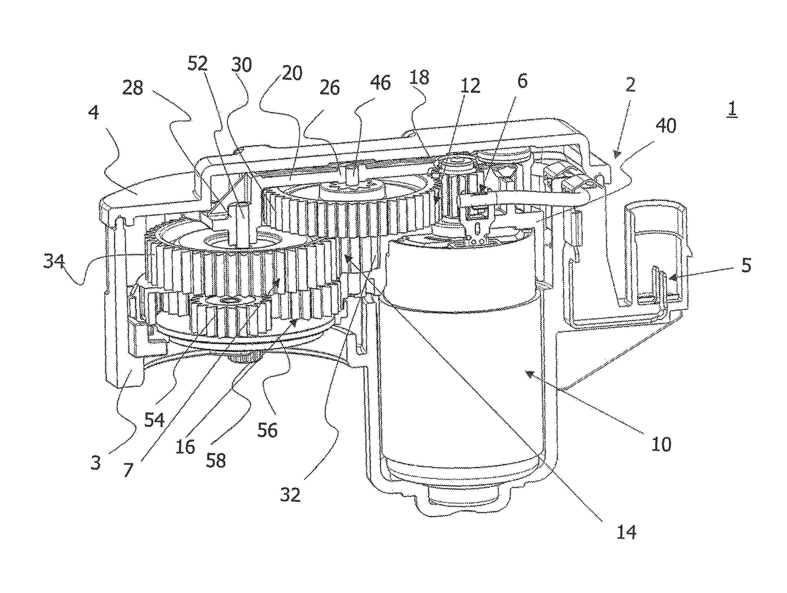
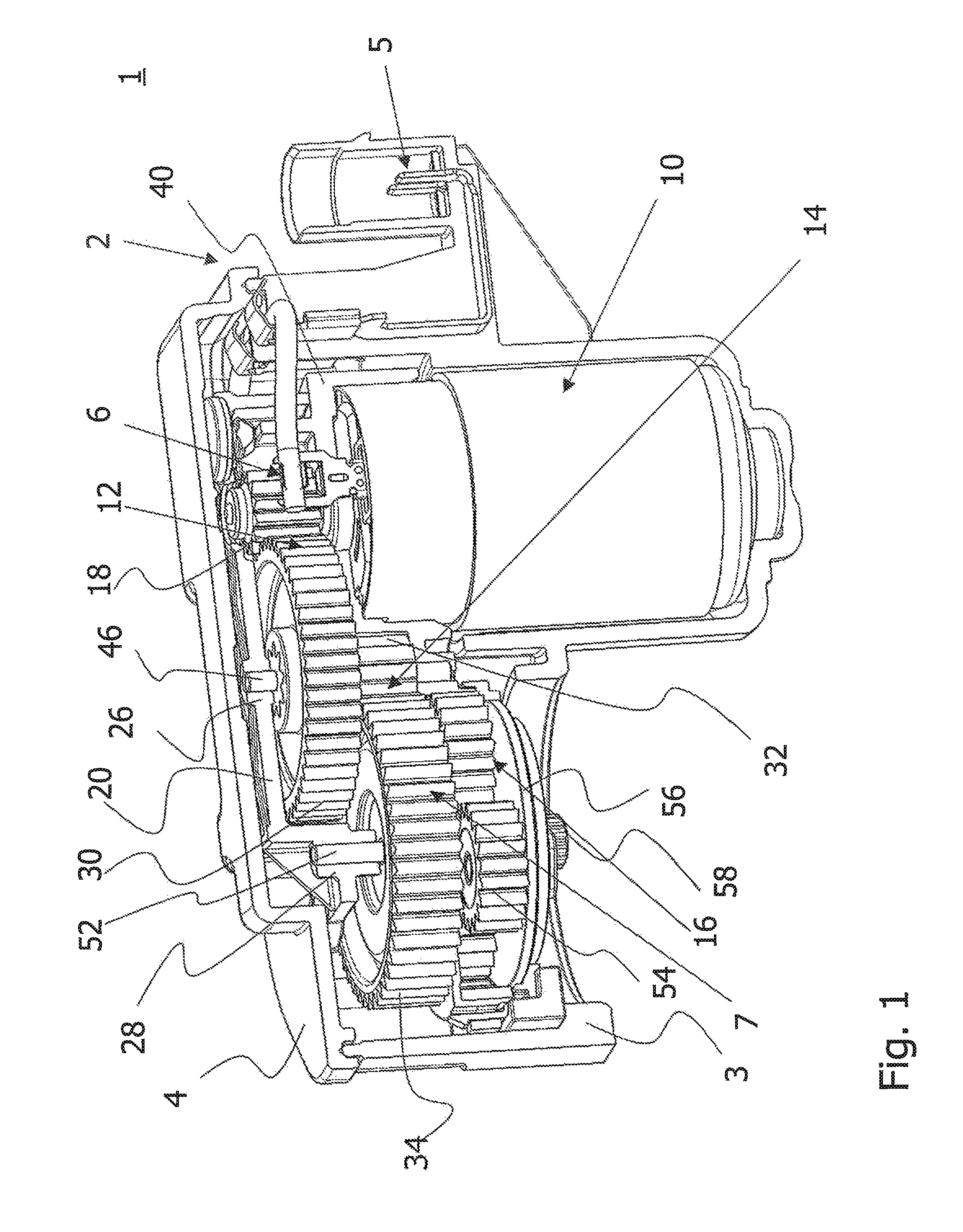
[0031]FIG. 1 shows, in a perspective representation, essential components of an embodiment of an electromechanical brake actuator 1. The electromechanical brake actuator 1 exhibits a subassembly 6 which has been supported in cushioning manner in a protective housing 2. The subassembly 6 comprises a drive device 10, with a drive shaft 11, and a gearing device 7 coupled therewith. The gearing device 7 has three successive stages, the first and second gearing stages 12, 14 taking the form of toothed-wheel gearings, and th...


PUM


Abstract

The invention relates to a subassembly for a brake actuator, which is provided for an electromechanically operated parking brake. The subassembly comprises a drive device and a gearing device, which comprises in succession a first, second and third gear stage for transmitting a torque generated by the drive device. The first gear stage is designed in the form of a gearwheel or belt drive, the second gear stage is designed in the form of a gearwheel mechanism, and the third gear stage is designed in the form of a planetary gear, wherein a planet carrier of the third gear stage receives a first gearing shaft for a sun gear of the planetary gear and an output-side gearwheel of the second gear stage that is coupled to rotate with the sun gear, and bearing elements for planet gears of the third gear stage. The invention further relates to an electromechanical brake actuator and to an electric parking brake, which include the sub-assembly.

Description

CROSS-REFERENCE TO RELATED APPLICATIONS[0001]This application is a national stage of International Application No. PCT / EP2011 / 003314 filed Jul. 4, 2011, the disclosures of which are incorporated herein by reference in entirety, and which claimed priority to German Patent Application No. DE 10 2010 032 053.6 filed Jul. 23, 2010, the disclosures of which are incorporated herein by reference in entirety.BACKGROUND OF THE INVENTION[0002]The present invention relates to the field of motor-vehicle brakes. More precisely, the invention relates to an improved structure of a subassembly of a brake actuator that has been provided for an electromechanically operated parking brake or an electromechanically operated service brake.[0003]Electrically operated parking brakes (EPB) are increasingly replacing conventional parking brakes, which via cables convert a force applied by the driver into a locking force at wheel brakes of the vehicle. The advantage of electric parking brakes lies in their ca...

Claims


Application Information

Patent Timeline
Patent Type & Authority Patents(United States)
IPC IPC(8): F16H48/06F16D65/28F16H1/28F16D121/24F16D125/34F16D125/48F16D125/50
CPCF16H1/28F16D65/28F16D2121/24F16D2125/34F16D2125/48F16D2125/50F16D65/00F16D65/14F16D65/18
Inventor DETTENBERGER, STEFANPOERTZGEN, GREGOR
Owner LUCAS AUTOMOTIVE GMBH
Why Eureka
Try Eureka