hydraulic buffer
A technology of hydraulic buffers and regulators, applied in the field of hydraulic buffers, can solve the problems of limiting the longest elongation stroke, changes, etc.
- Summary
- Abstract
- Description
- Claims
- Application Information
AI Technical Summary
Problems solved by technology
Method used
Image
Examples
Embodiment 1)
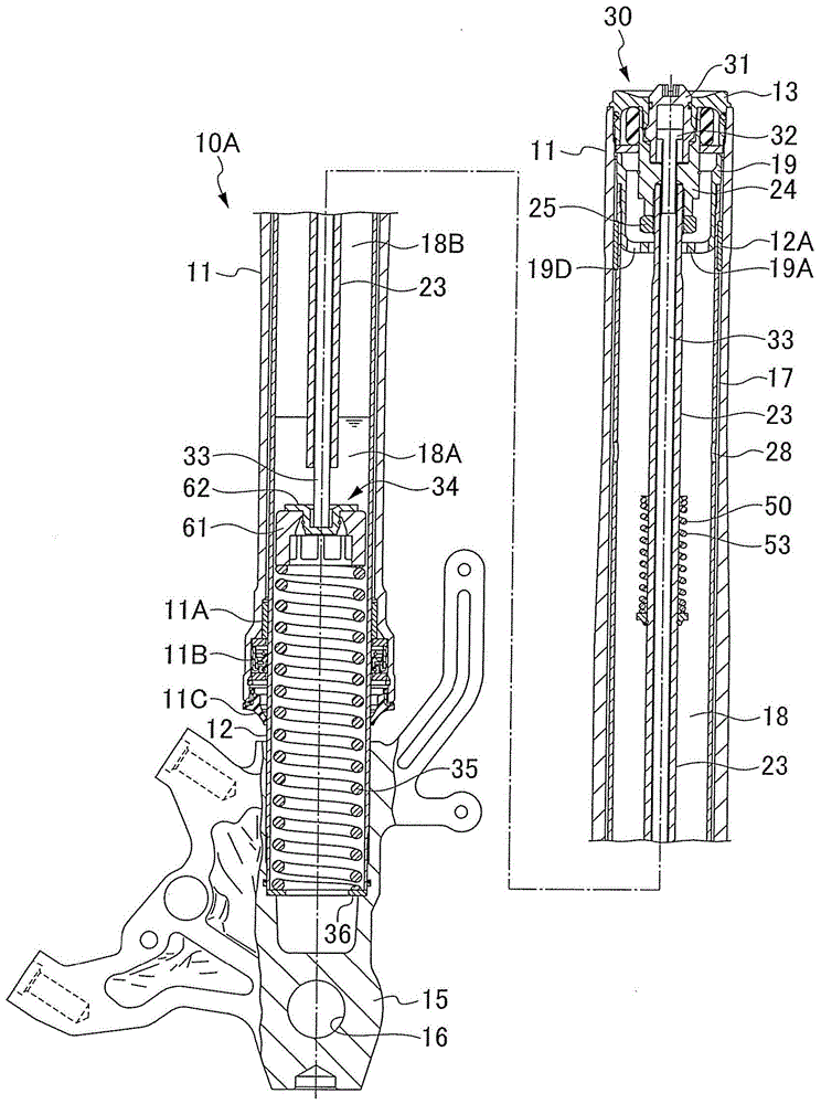
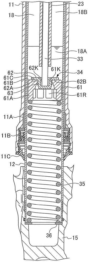
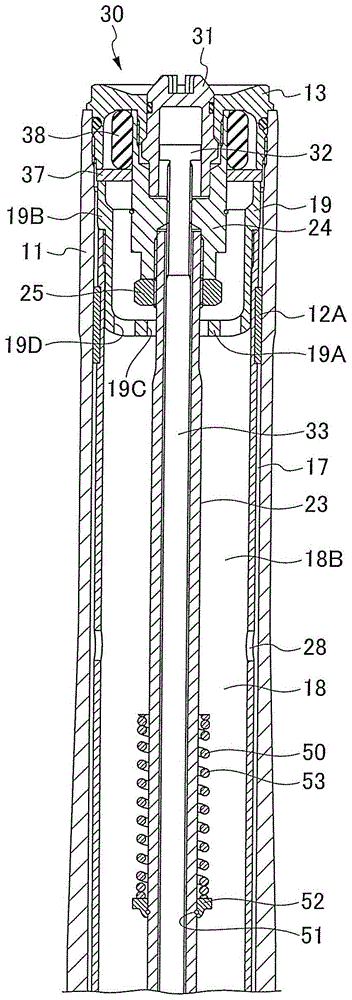
[0054] (Example 1) ( Figure 1 to Figure 6 )
[0055] figure 1 The shown hydraulic shock absorber 10A constitutes at least one of the left and right legs of a front fork of a motorcycle or the like, and is a spring leg having a built-in suspension spring 35 without a built-in damper. At this time, the other of the left and right legs of the front fork is constituted by a damper leg having a built-in damper. However, the left and right legs can also be spring legs.
[0056] The hydraulic shock absorber 10A constitutes an inverted front fork with a vehicle body side tube as an outer tube 11 and a wheel side tube as an inner tube 12 . However, the hydraulic shock absorber 10A may also be configured as an upright type front fork having a vehicle body side tube as an inner tube and a wheel side tube as an outer tube.
[0057] Hydraulic shock absorber 10A as Figure 1 ~ Figure 3 As shown, through the lower guide sleeve 11A fixed on the inner circumference of the lower end openi...
Embodiment 2)
[0088] (Example 2) ( Figure 7 , Figure 8 )
[0089] Figure 7 , Figure 8 The hydraulic shock absorber 10B of Embodiment 2 shown with Figure 1 to Figure 6 The hydraulic shock absorber 10A of the first embodiment shown is substantially different in that the operating oil chamber 21 is divided into the lower part than the partition wall part 19A of the partition wall member 19 provided on the inner periphery of the upper end side of the inner pipe 12, and the upper part The zoned oil storage chamber 22 is in fixed sliding contact with the piston 26 on the inner circumference of the inner tube 12 on the front end of the hollow rod 23 . Hereinafter, the hydraulic shock absorber 10B will be described in detail, and in the hydraulic shock absorber 10B, the same components as in the hydraulic shock absorber 10A are given the same reference numerals.
[0090] The shock absorber 10B is an inverted front fork in which the outer tube 11 is arranged on the vehicle body side and th...
Embodiment 3)
[0112] (Example 3) ( Figure 9 ~ Figure 12 )
[0113] Figure 9 ~ Figure 12 The hydraulic shock absorber 100 of the third embodiment shown constitutes a front fork of a motorcycle or the like. The hydraulic shock absorber 100 constitutes an inverted front fork with a vehicle body side tube as an outer tube 111 and a wheel side tube as an inner tube 112 . However, the hydraulic shock absorber 100 may also be configured as an upright type front fork having a vehicle body side tube as an inner tube and a wheel side tube as an outer tube.
[0114] Hydraulic shock absorber 100 such as Figure 9 ~ Figure 12 As shown in FIG. It fits freely inside the outer tube 111 . 111B is an oil seal, and 111C is a dust seal. The outer cylinder portion 113A of the cap 113 is screwed and fixed to the upper end opening of the outer tube 111 in a sealed state by an O-ring, and a vehicle body side mounting member is provided on the outer periphery of the outer tube 111 . A bottom bracket 115 is...
PUM
 Abstract
Description
Claims
Application Information
 - R&D
- Intellectual Property
- Life Sciences
- Materials
- Tech Scout
- Unparalleled Data Quality
- Higher Quality Content
- 60% Fewer Hallucinations
Browse by: Latest US Patents, China's latest patents, Technical Efficacy Thesaurus, Application Domain, Technology Topic, Popular Technical Reports.
© 2025 PatSnap. All rights reserved.Legal|Privacy policy|Modern Slavery Act Transparency Statement|Sitemap|About US| Contact US: help@patsnap.com


