
Fiber broken filament collecting device and using method thereof

A collection device and fiber technology, applied in the direction of measuring devices, instruments, scientific instruments, etc., can solve the problems of insufficient collection of fiber wool and inaccurate data of wool yarn, and achieve accurate wear resistance test results, good collection effect, Avoid the effect of abrasion

Pending Publication Date: 2021-03-23
RES INST OF PHYSICAL & CHEM ENG OF NUCLEAR IND
View PDF1 Cites 0 Cited by
  • Summary
  • Abstract
  • Description
  • Claims
  • Application Information

AI Technical Summary

Problems solved by technology

[0006] The purpose of the present invention is to provide a fiber wool collection device for the defects such as insufficient collection of fiber wool and inaccurate data of wool volume in the fiber abrasion resistance test process. The collection device includes a base, an upper pressing block and two Sheet collecting sheet, under the stable load provided by the base and the upper pressing block, the fiber bundle passes through two collecting sheets horizontally, and the fiber wool is collected on the collecting sheet, and then passes through the fiber channel through the fiber wool collecting device to complete the collection of wool Work

Method used


Image

  • Fiber broken filament collecting device and using method thereof
  • Fiber broken filament collecting device and using method thereof
  • Fiber broken filament collecting device and using method thereof

Examples


Embodiment 1

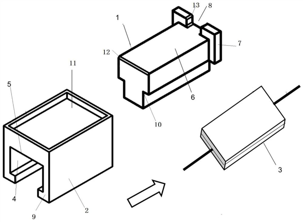
[0034] A fiber fluff collection device, comprising an upper pressing block 2, a base 1 nested in the upper pressing block 2, and two collecting pieces 3 placed on the base 1 and positioned by pressing the upper pressing block 2;

[0035] Wherein: the upper pressing block 2 is formed with a slot 4 for insertion of the base 1, the slot 4 is in the same pulling direction as the fiber bundle, and the top of the slot 4 forms a horizontal pressing surface 5, A horizontal upper support surface 6 is formed on the top of the base 1 , and two collection sheets 3 are located between the lower pressing surface 5 and the upper support surface 6 , and the fibers pass through horizontally between the two collection sheets 3 .

[0036] The surface of the lower pressing surface 5 and the upper supporting surface 6 is horizontal and smooth, and there is a gap of 2-15mm between them, which ensures that the collecting sheet has a corresponding space to be placed, and it is flat and free of pleats ...

Embodiment 2

[0044] This embodiment introduces its preferred structure on the basis of Embodiment 1.

[0045] As a preferred mode, the end of the base 1 in the direction in which the fiber bundle leaves is fixed with a block 7 that limits the position of the upper pressing block 2 in the horizontal direction, and the middle of the block 7 is provided with a Fiber channel 8.

[0046] The height of the block 7 is 2-15mm, and the height of the block 7 is greater than the height of the gap between the pressing surface 5 and the upper supporting surface 6, which can prevent the upper pressing block from passing through the block 7. The width of the fiber channel 8 is 5-20 mm, and the fiber channel ensures the normal passage of the fiber bundle.

[0047] The block 7 prevents the upper pressing block 2 or the collecting sheet 3 from horizontally displacing when there is a large traction force and pulling speed, and prevents the collecting sheet 3 from wrinkling or being cheap or even being dragg...

Embodiment 3

[0055] This embodiment introduces the fixing plate on the basis of Embodiment 1 and Embodiment 2.

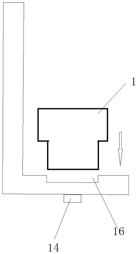
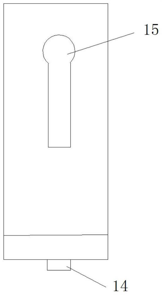
[0056] like figure 2 As shown, it also includes an L-shaped fixing plate, the bottom horizontal plate of the L-shaped fixing plate is provided with a groove 16 for accommodating the bottom of the T-shaped base 1, and the bottom of the L-shaped fixing plate is provided with a fixing nut 14, In order to fix the T-shaped base 1 on the L-shaped fixing plate, a strip hole 15 is formed on the vertical plate of the L-shaped fixing plate to pass the L-shaped fixing plate through the strip. The hole 15 is fixed on the wool wear resistance test device with a nut.


PUM


Abstract

The invention discloses a fiber broken filament collecting device. The device comprises a base, an upper pressing block and two collecting pieces; under the stable load provided by the base and the upper pressing block, a fiber bundle horizontally penetrates through the two collecting pieces, fiber broken filaments on the collecting pieces are collected, and then the fiber bundle penetrates out ofthe fiber broken filament collecting device through a fiber channel, and therefore, broken filament collecting work is completed. Polyester sponge pieces are used as the collecting pieces, so that broken filaments generated during fiber abrasion resistance testing are effectively collected, no obvious broken filaments exist on the surface of the fiber bundle after the fiber bundle passes through,a good collecting effect is achieved, and reliable data are provided for fiber abrasion resistance testing evaluation. By means of the device, a fiber broken filament collection method is simple to operate, and a foundation is provided for the research of a fiber wear resistance evaluation method and the development of a special device .

Description

technical field [0001] The invention relates to the technical field of material testing, in particular to a fiber fuzz collecting device and a using method thereof. Background technique [0002] Due to the advantages of good mechanical strength and stability and long-term storage, fiber composite materials have been developed rapidly in recent years, especially in aerospace, medical, electronics, machinery and other fields. Among them, the wear resistance of fibers is of great significance to the application of fibers. Its accurate characterization helps to obtain more accurate design parameters in the design process of composite products and obtain products with excellent performance. At present, there is no universally applicable, simple and effective collection device for the fiber fuzz obtained in the fiber abrasion resistance test. Chinese patent CN 105445131 A discloses a method for testing the wear resistance of fiber tow and a method for collecting and judging fluff...

Claims


Application Information

Patent Timeline
Patent Type & Authority Applications(China)
IPC IPC(8): G01N3/56G01N3/02
CPCG01N3/56G01N3/02G01N2203/028
Inventor 李武胜贾力伟杨国良
Owner RES INST OF PHYSICAL & CHEM ENG OF NUCLEAR IND
Learn More