
Barrier cable gland

A technology of cable sealing and cable sheathing, which is applied to the installation of cable terminals, cable accessories, and cables, and can solve problems such as the trouble of applying liquid resin

Active Publication Date: 2013-10-30
CCG AUSTRALASIA
View PDF9 Cites 2 Cited by
  • Summary
  • Abstract
  • Description
  • Claims
  • Application Information

AI Technical Summary

Problems solved by technology

As a result, the application of liquid resin can become rather cumbersome

Method used


Image

  • Barrier cable gland
  • Barrier cable gland
  • Barrier cable gland

Examples


Embodiment Construction

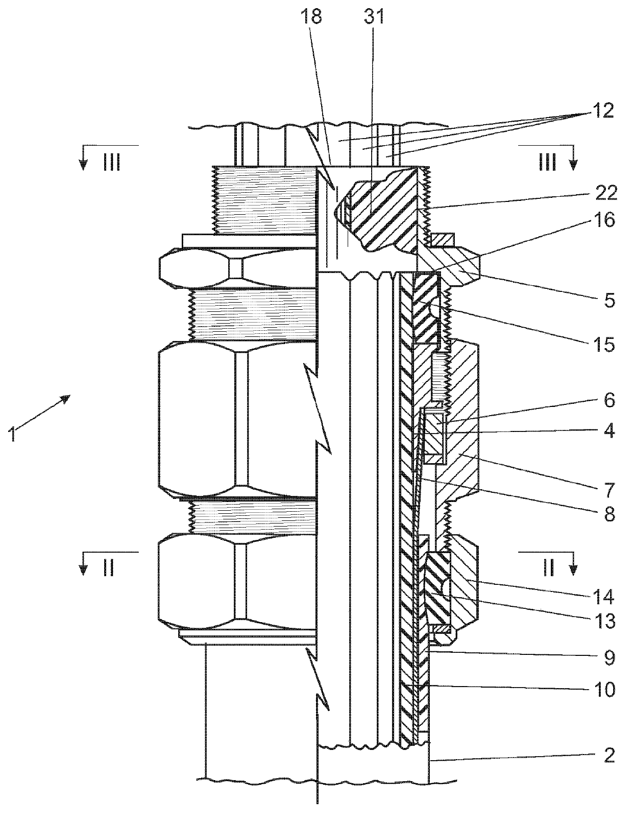
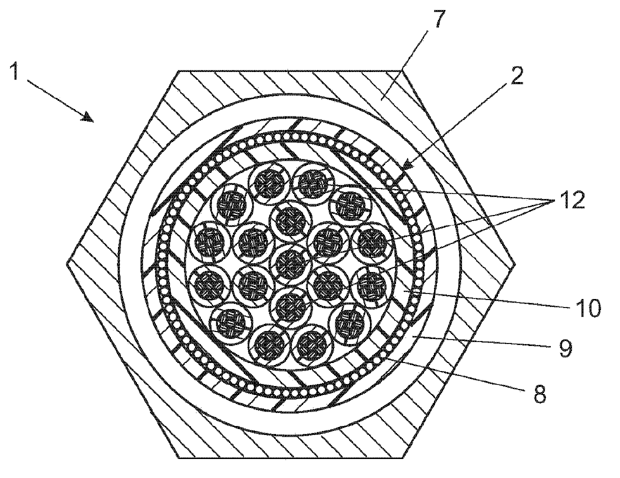
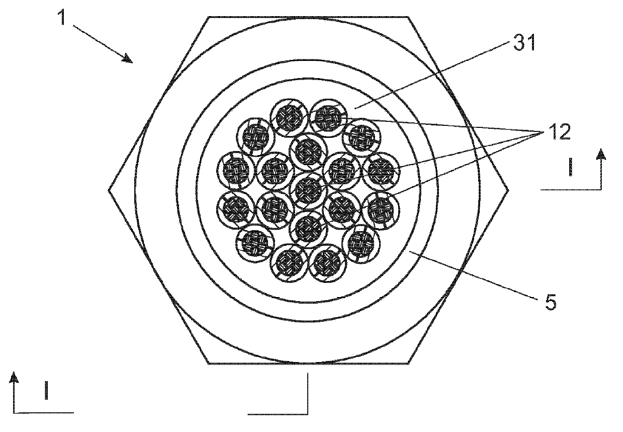
[0028] in the attached Figure 1 to Figure 3 In an application of the invention showing its results, the method of installing a barrier cable gland according to the invention is applied to a cable gland of the type shown in the drawings and described below.

[0029] Such cable glands, generally indicated by the number (1), are made for use on armored or shielded (here referred to as "armored", regardless of their exact nature) cables (2), which have armored clamps Assembly, the armor clamp assembly generally includes an armor clamp cone (4) that preferably remains restrained relative to the inner tubular body (5) and a mating clamp ring that preferably remains restrained relative to the outer tubular body (7) 6). The armor clamp assembly is operable to push the armor clamp cone into a mating clamp ring to securely clamp the cable passing between the outer electrically insulating sheath (9) and the inner electrically insulating sheath (10) Armor Wire (8). This is accomplishe...


PUM


Abstract

A barrier cable gland has an inner tubular body 5, which screw-threadedly engages an outer tubular body 7 and / or a union nut 14. A compression seal 13 engages the cable sheath 9. The open end of the inner tubular body is turned uppermost and a curable liquid two component resin mix is introduced into a cavity defined by an inwardly directed surface of the inner tubular body and the compression seal at a lower end thereof. A release layer or film is applied to the inwardly directed surface. The resin mix may be introduced by way of a double syringe wherein each of the two liquid components of the resin is separately packaged in a syringe barrel and an elongated mixing nozzle is fitted to the double syringe to effect mixing as resin components are ejected into and through the mixing nozzle. The release layer or film prevents the resin from bonding to the inner tubular body and so allows the gland to be inspected.

Description

technical field [0001] The present invention relates to a barrier cable gland of this type that can be used in hazardous areas where flammable or explosive gases may be able to enter the spaces between electrically insulated conductors, which within the electrically insulating sheath that surrounds them. [0002] More particularly, but not exclusively, the present invention relates to barrier cable glands, which are particularly, but not exclusively, adapted for use with armored or shielded cables in which a conductive armor wire or shield is sandwiched between an electrically insulating inner sheath. between the sleeve and the electrically insulating outer sheath. [0003] The application of the present invention thus extends to barrier terminated cable glands used in conjunction with electrical cables having any of a number of different forms, traditional more robust helically wound armor wires or less robust shielded wires, As well as wires that are even completely unarmo...

Claims


Application Information

Patent Timeline
IPC IPC(8): H02G15/04H02G15/06
CPCH02G15/046H02G15/003H02G15/04F16J15/00
Inventor 尼古拉斯·弗朗茨·爱德华·拉金格
Owner CCG AUSTRALASIA
Learn More