Sensor circuit and calibration method

A sensor circuit and sensor technology, applied in the field of microphones, can solve the problems of no significant improvement in CMOS noise, options and cooling costs or high power, and increased input noise of CMOS readout circuits.

Active Publication Date: 2013-10-30
NXP BV
View PDF4 Cites 16 Cited by
  • Summary
  • Abstract
  • Description
  • Claims
  • Application Information

AI Technical Summary

Problems solved by technology

Unfortunately, when the input capacitance becomes small, the input noise of the CMOS readout circuit increases
New technology does not significantly improve this CMOS noise
Options such as bipolar JFET devices and cooling are more expensive in terms of cost or power

Method used


Image

  • Sensor circuit and calibration method
  • Sensor circuit and calibration method
  • Sensor circuit and calibration method

Examples


Embodiment Construction

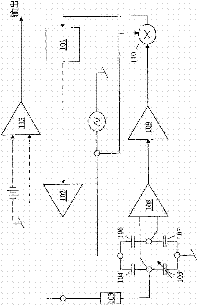
[0060] The present invention provides a sensor circuit using an AC signal source for generating a bias signal. A sensor having an impedance sensitive to the physical property to be measured is coupled between the signal source and the amplifier. A feedback loop structure around the amplifier controls the bias applied to the sensor element, wherein the feedback loop structure includes a first feedback control path for setting the bias level to a reference bias level, and a second feedback A control path for setting the reference bias level, wherein the first feedback control is faster than the second feedback control. Such a two-stage feedback system makes it possible to quickly set the bias point as a reference value in order to provide stable operation, and to adjust the reference point so that it can, for example, be closer to the limit of stability.

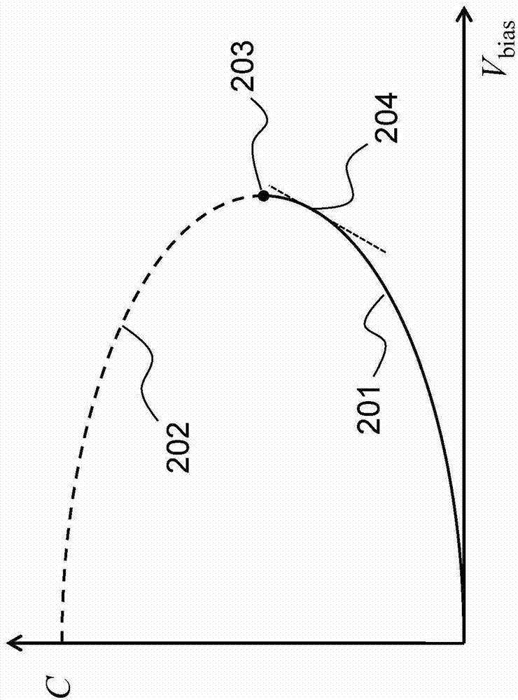
[0061] The noise level is reduced by increasing the electromechanical gain of the sensor. This is achieved by biasing clos...


PUM


Abstract

The invention provides a sensor circuit and calibration method. A read out circuit for a sensor uses a feedback loop to bias the sensor to a desired operating point, such as the maximal possible sensitivity, but without the problem of an instable sensor position as known for the conventional read-out with constant charge. The reference bias to which the circuit is controlled is also varied using feedback control, but with a slower response than the main bias control feedback loop.

Description

technical field [0001] The invention relates to MEMS capacitive sensors, eg for use as microphones. Background technique [0002] Condenser microphones consist of two diaphragms: one that is excited by sound pressure and a perforated membrane that forms a counter electrode ("back plate") that does not move in response to sound pressure because the Perforations make it acoustically transparent. The perforations allow the first diaphragm to move without pressure buildup in the volume between the diaphragm and the backplate. [0003] figure 1 Top and cross-sectional views of a (MEMS) condenser microphone are shown. [0004] The silicon substrate 1 has openings exposing the portion of the movable diaphragm 3 that is sensitive to sound pressure. Above the (optional) insulator 2 a movable diaphragm is formed. A backplate 5 (fixed film) is suspended above another insulator 4 and is perforated with a regular pattern of holes. Electrode connections 6, 7 are connected to the two...

Claims


Application Information

Patent Timeline
Patent Type & Authority Applications(China)
IPC IPC(8): H04R3/00H04R29/00
CPCG01D5/24H04R3/02G01R17/08G01L9/12G01R27/2605G01P15/125H04R3/06H04R2410/07
Inventor 克劳斯·莱曼特温·范利庞雷默克·亨里克斯·威廉默斯·皮内伯格伊丽丝·博米纳-西尔金斯罗伯特·H·M·范费尔德温
Owner NXP BV
Why Eureka
Try Eureka