Galvanostat with mother valve and child valve

A technology of a constant current device and a mother and child valve, which is applied in the field of constant current devices, can solve the problems of increased overall volume, high cost, and inability to install the constant pressure current device.

Inactive Publication Date: 2013-11-06
李能
View PDF12 Cites 3 Cited by
  • Summary
  • Abstract
  • Description
  • Claims
  • Application Information

AI Technical Summary

Problems solved by technology

The disadvantage is that when working, the valve stem often protrudes from the base, resulting in an increase in the overall volume of the constant pressure regulator and a correspondingly high cost. It cannot be installed on some specific faucets.

Method used


Image

  • Galvanostat with mother valve and child valve
  • Galvanostat with mother valve and child valve
  • Galvanostat with mother valve and child valve

Examples


Embodiment Construction

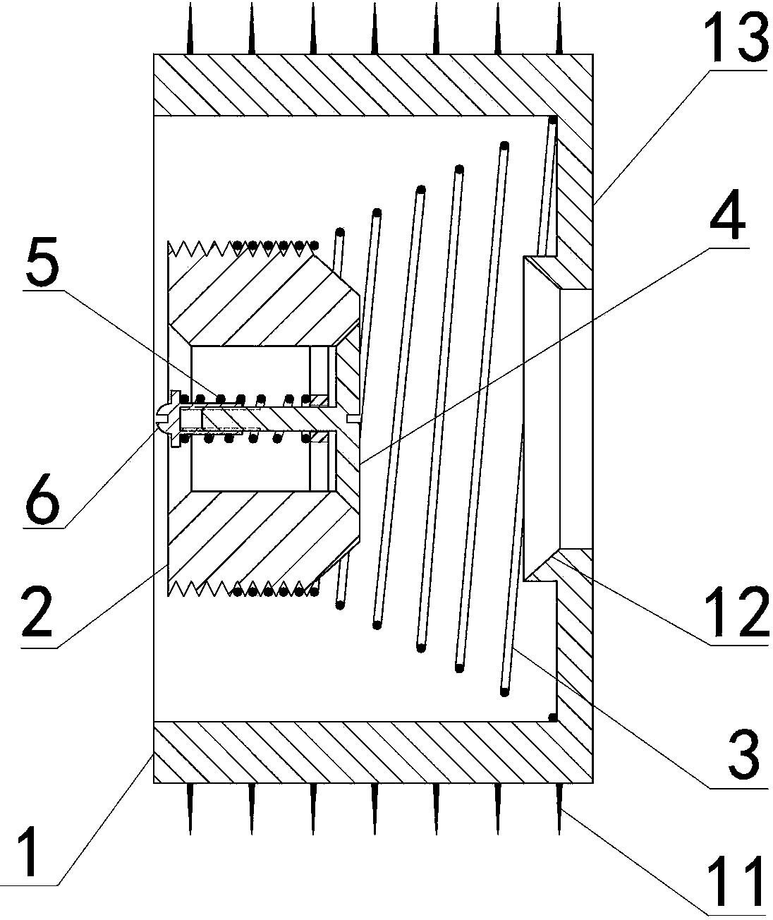
[0024] Such as figure 1 As shown, the flow regulator with mother and child valves is mainly composed of a base 1, a mother valve 2 and an elastic device 3 placed in the base 1; the outer wall of the base 1 is provided with a protruding sealing pleat or thread 11, which is inserted into the tap water Make the outer wall of the base 1 form a tight fit with the inner wall of the water pipe when the pipe is installed.

[0025] The outlet aperture of the base 1 is smaller than the inlet, and there is a blocking piece 13 connected with the base 1 around the outlet.

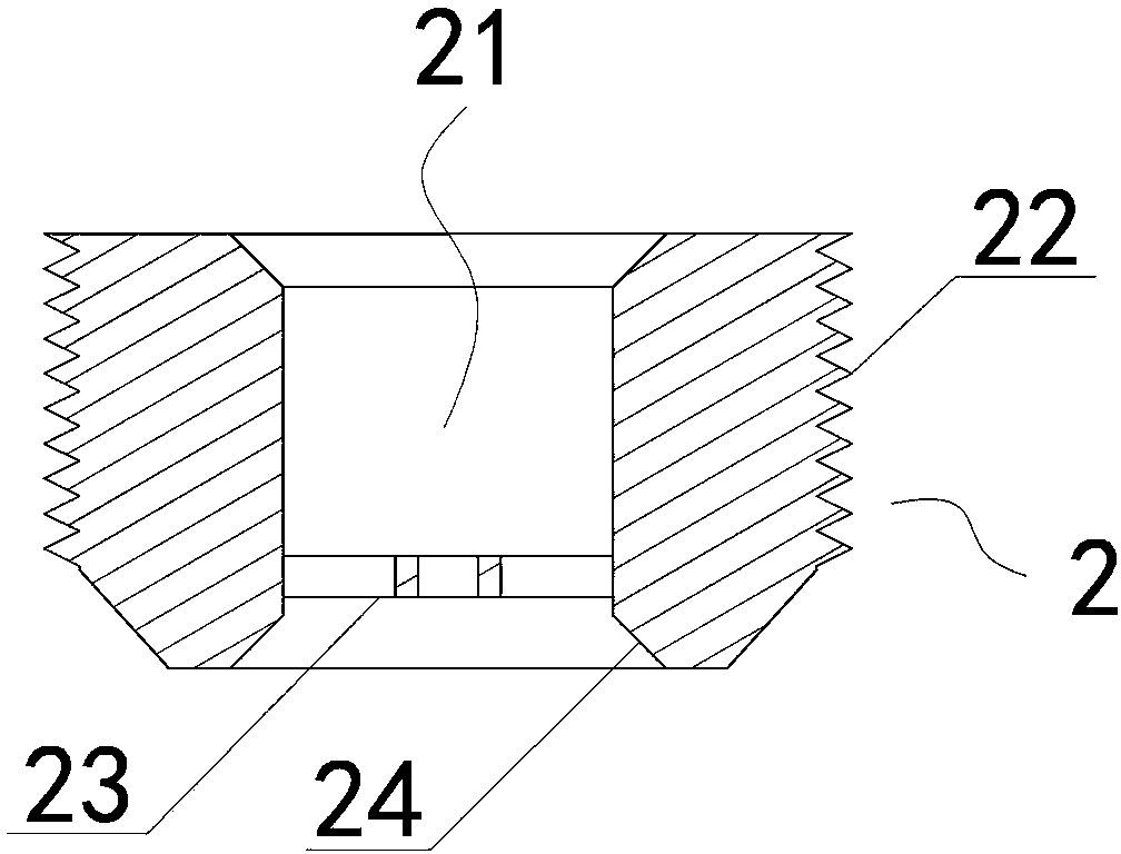
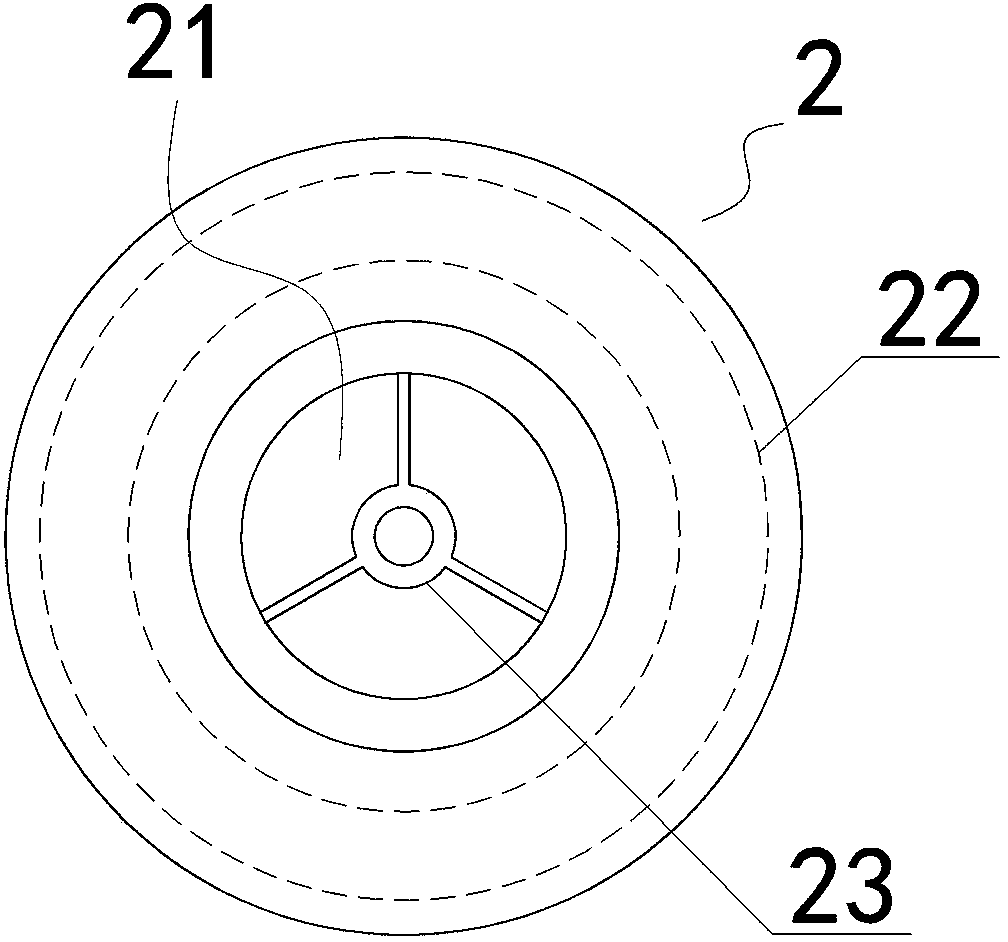
[0026] Such as figure 2 with image 3 As shown, the mother valve 2 includes a cylindrical base body and a cone with the end surface of the base body as the bottom surface. An overflow hole 21 is provided along the axis of the mother valve 2. The outer wall of the base valve 2 is provided with threads 22. The mother valve 2 is pressed The cone enters the base 1 from the inlet end in such a way that the front base is ...


PUM


Abstract

A galvanostat with a mother valve and a child valve mainly comprises a base as well as the mother valve and an elastic device which are arranged in the base, wherein an adjusting device is arranged in an overflowing hole of the mother valve, and used for adjusting the flow when an outlet is blocked by the mother valve driven by pressure.

Description

technical field [0001] The invention relates to a constant flow device with mother and child valves, which can independently set the gas output or liquid output according to the needs of the user, and belongs to the optimization technology of the gas supply system and the liquid supply system. Background technique [0002] Liquid supply system, taking tap water as an example: there are generally two ways to supply water to buildings at present, one is to use a booster pump to send water from bottom to top, and the other is to install a water tank on the roof and use the water level difference to send water from top to top. The way of delivery. Regardless of the water delivery method, the water pressure on different floors will be different, resulting in different water output on different floors. [0003] Patent No. 200520142654.4 discloses a device that uses water pressure to automatically adjust the water output of tap water. The advantage is that it realizes the functio...

Claims


Application Information

Patent Timeline
Patent Type & Authority Applications(China)
IPC IPC(8): F16K17/30
CPCF16K1/526F16K17/30
Inventor 李耀强
Owner 李能
Why Eureka
Try Eureka