A solar film thermal transfer marking machine

A thermal transfer printing and marking machine technology, which is applied to transfer materials, printing, power transmission devices, etc., can solve the problems of inability to place large blocks, high manufacturing costs, and no heat insulation devices, etc., and achieves simple structure and guaranteed equipment, cost savings

Active Publication Date: 2016-01-13
苏州威仕薄膜科技有限公司
View PDF10 Cites 0 Cited by
  • Summary
  • Abstract
  • Description
  • Claims
  • Application Information

AI Technical Summary

Problems solved by technology

[0002] Existing carbon ribbon marking machines generally use pneumatic push to mark, but the pneumatic push uses a cylinder to push, and its impact force is large. At the same time, there are three marking blocks formed in the existing marking machine. The side-by-side long slots make it possible to place only split-type multiple letter-shaped small blocks. The general length and width of the small blocks are only about 0.5cm, and it is impossible to place some large ones with engraved patterns on the rectangular upper plane. Block body, so that it can only print some letters and dates, and its marking is single, which cannot meet the different needs of customers
[0003] The heat generated by the heating block on the sliding block of the existing marking machine will be transmitted to the entire support plate through the sliding block, and there is no special heat insulation device
[0004] At the same time, the existing marking mechanism is generally driven by dual motors, one for winding and one for feeding, and its manufacturing cost is high

Method used


Image

  • A solar film thermal transfer marking machine
  • A solar film thermal transfer marking machine
  • A solar film thermal transfer marking machine

Examples


Embodiment Construction

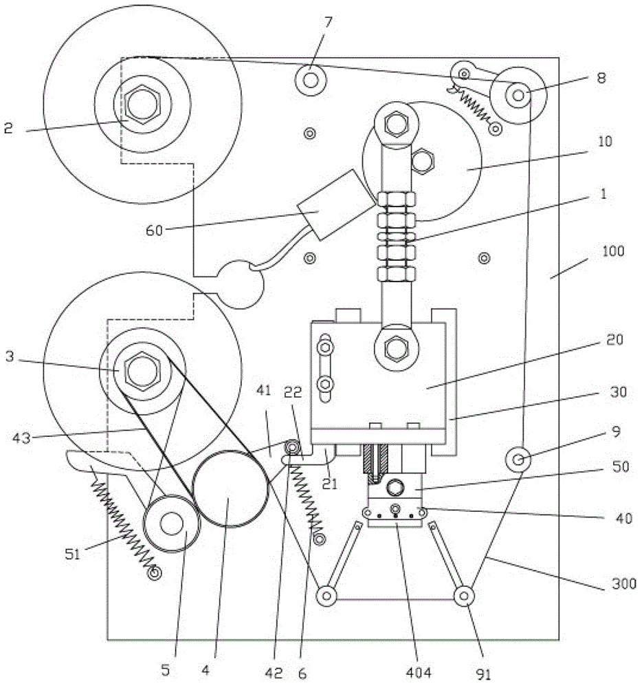
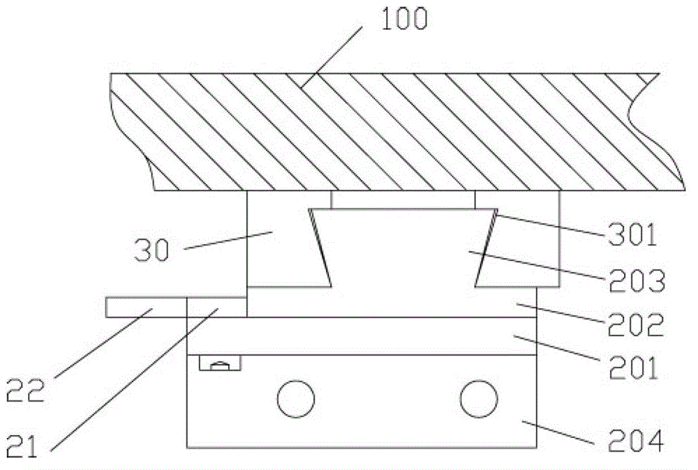
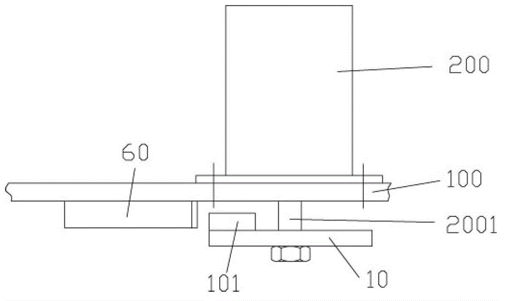
[0025] Examples, see e.g. Figures 1 to 6 As shown, a solar film thermal transfer marking machine includes a support plate 100 and a servo motor 200, the servo motor 200 is fixed on the back of the support plate 100, and the rotating shaft 2001 of the servo motor 200 is inserted into the support plate 100 and extends out On the front of the support plate 100, the top of the rotating shaft 2001 is fixed with a rotating disc 10, the rotating disc 10 is at the middle and upper part of the supporting plate 100, the adjusting rod 1 is below the rotating disc 10, and the upper end of the adjusting rod 1 is hinged on the side of the rotating disc 10. The lower end of the adjusting rod 1 is hinged on the sliding block 20 below the adjusting rod 1, the sliding block 20 is inserted into the sliding rail 30 fixed on the front of the support plate 100, the bottom of the sliding block 20 is fixed with a heating block 50, heating The bottom surface of the block 50 is fixed with a marking de...


PUM


Abstract

The invention discloses a heat-transfer-printing marking machine for solar films. A sliding block is fixed through an adjustment lever, a heating block is fixed at the bottom of the sliding block, a marking device is fixed on the bottom surface of the heating block, according to the structure of the marking device, a rectangular through groove is formed in the upper plane of a block, a left baffle and a right baffle are fixed at two ends of the block, a marking block is inserted in the middle of the block, marking patterns are engraved in the upper plane of the marking block, the upper plane of the marking block is higher than that of the block, rod portions of a plurality of bolts are screwed on the right baffle and penetrate the right baffle to abut against the right side wall of the marking block, the left side wall of the marking block abuts against the inner wall of the left baffle, and the bottom surface of the block is fixed on the bottom surface of the heating block. The marking block of the marking machine moves up and down and is small in impact force, meanwhile, the rectangular through groove of the marking device can arrange the integrated marking block, and various patterns and combined letters can be engraved in the upper plane of the integrated marking block, so that requirements of different clients can be met.

Description

Technical field: [0001] The invention relates to the technical field of marking machine equipment, and more specifically relates to a solar film thermal transfer marking machine. Background technique: [0002] Existing carbon ribbon marking machines generally use pneumatic push to mark, but the pneumatic push uses a cylinder to push, and its impact force is large. At the same time, there are three marking blocks formed in the existing marking machine. The side-by-side long slots make it possible to place only split-type multiple letter-shaped small blocks. The general length and width of the small blocks are only about 0.5cm, and it is impossible to place some large ones with engraved patterns on the rectangular upper plane. The block body makes it only possible to type some letters and dates, and its marking is single, which cannot meet the different needs of customers. [0003] The heat produced by the heating block on the sliding block of the existing marking machine can...

Claims


Application Information

Patent Timeline
Patent Type & Authority Patents(China)
IPC IPC(8): B41J2/315B41J25/312
Inventor 孙加元
Owner 苏州威仕薄膜科技有限公司
Why Eureka
Try Eureka