
Occlusion of a vessel

a vessel and occlusion technology, applied in the field of occlusion of vessels, can solve the problems of limited attempts to treat such occlusions with balloon angioplasty, difficult treatment of arteries, permanent brain damage, etc., and achieve the effect of not putting patients at risk

Inactive Publication Date: 2006-02-07
MEDTRONIC VASCULAR INC
View PDF124 Cites 129 Cited by
  • Summary
  • Abstract
  • Description
  • Claims
  • Application Information

AI Technical Summary

Benefits of technology

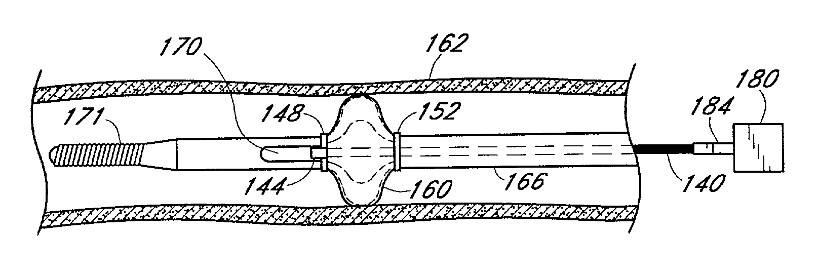
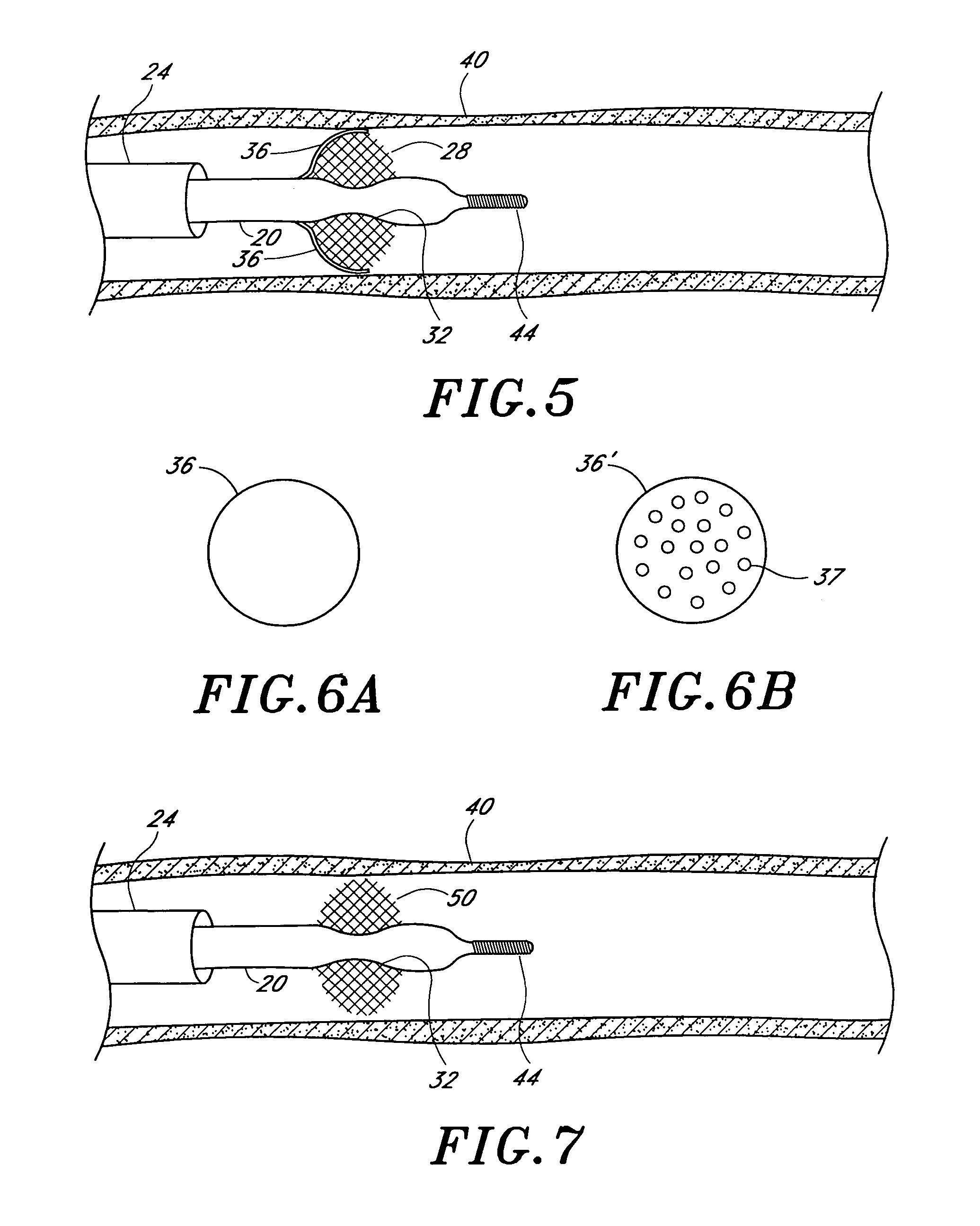
[0010]The present invention satisfies the need for a device that occludes a vessel, in particular, a vessel in a patient undergoing therapeutic or other medical treatment. Any one of a number of different expansion members are joined to one or more elongate members such as hypotubes to form a device that completely or partially occludes a vessel within a patient. The expansion member may be self-expanding, it may be expanded by engaging it with one of the elongate members, or it may be heated to cause it to expand. A membrane preferably surrounds the expansion member so that a seal is made between the membrane and the vessel. The perfusion of blood is allowed if the membrane is perforated. Partial occlusion may be obtained without a membrane if a suitable expansion member is chosen. In general, in one aspect of the present invention, there is provided an apparatus and method that can be used with approved diagnostic and therapeutic devices to reduce the chance of emboli migrating downstream. Alternatively, the expansion member may anchor an intravascular device within a vessel.

Problems solved by technology

However, such arteries have been very difficult to treat because of the possibility of dislodging plaque which can enter various arterial vessels of the brain and cause permanent brain damage.
Attempts to treat such occlusions with balloon angioplasty have been very limited because of such dangers.
Such surgical procedures have substantial risk associated with them which can lead to morbidity and mortality.
In other procedures, such as in angioplasty and in the treatment of peripheral arteries and veins, there is the possibility that the guide wires and catheters used in such procedures during deployment of the same may cause dislodgement of debris or emboli which can flow downstream and cause serious damage, such as stroke, if they occlude blood flow in smaller vessels.

Method used


Image

  • Occlusion of a vessel
  • Occlusion of a vessel
  • Occlusion of a vessel

Examples


Embodiment Construction

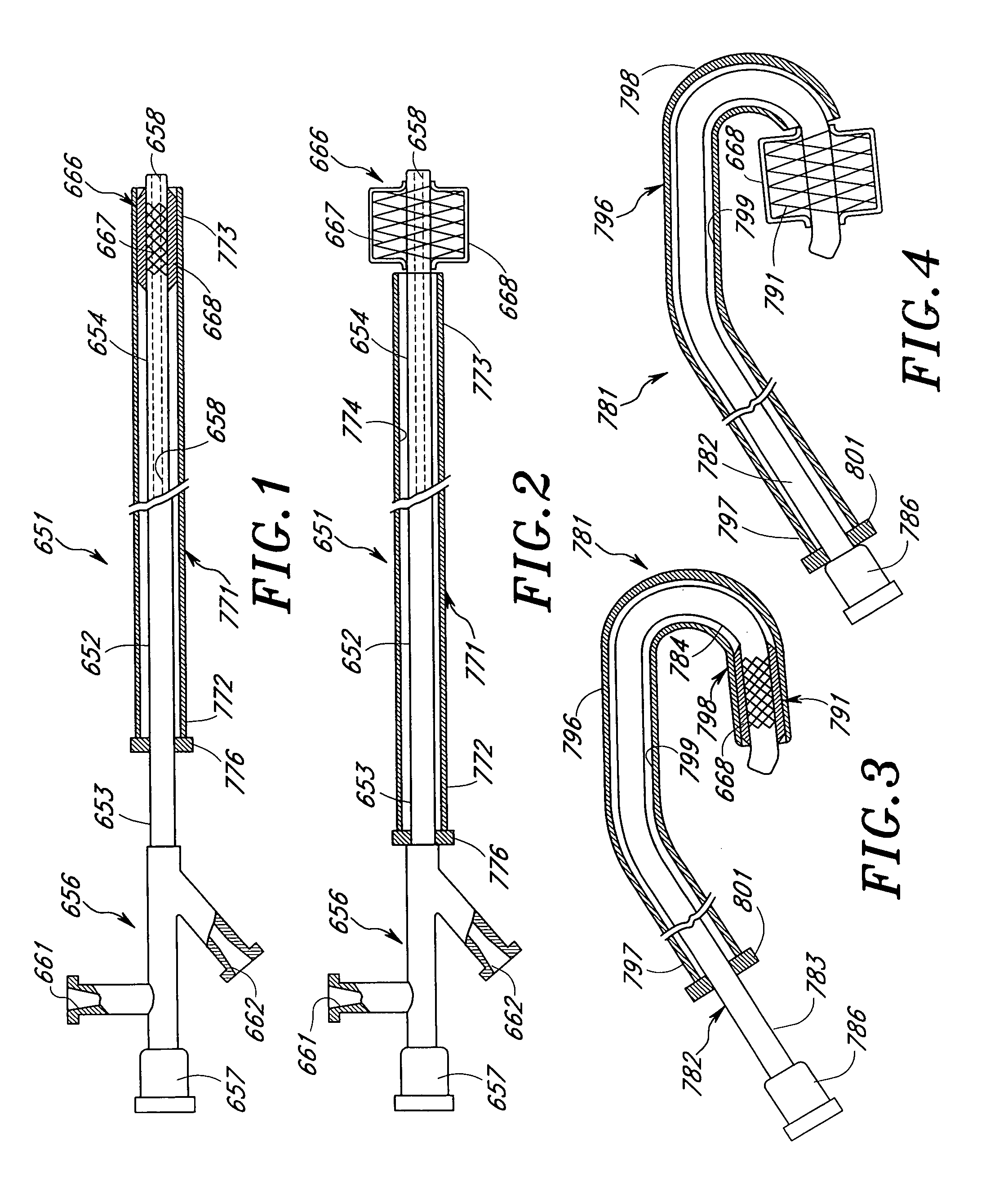
[0040]The expansion members discussed herein include braids, coils, ribs, ribbon-like structures, slotted tubes, and filter-like meshes. These expansion members may be partially covered or completely surrounded by a membrane or other covering to provide occlusion or sealing of the vessel. As used herein, “occlusion” or “sealing”, and the like, mean partial or complete blockage of fluid flow in a vascular segment, as it is sometimes preferable to allow perfusion. Moreover, such expansion members may be deployed by various mechanical means, electrical means or thermomechanical means, etc., as described herein. Expansion members that are deployed mechanically are preferably “spring-like” in nature, i.e. they are preferably resilient to facilitate their deployment or retraction.

Catheter Apparatuses and Self-Expanding Braids

[0041]One embodiment of a catheter apparatus incorporating the present invention for treating occluded vessels is shown in FIGS. 1 and 2. As shown therein, the cathet...


PUM


Abstract

A device for occluding a vessel employs one of a number of different expansion members joined to one or more elongate members. The expansion member may include a braid, one or more coils, ribs, a ribbon-like structure, a slotted tube, or a filter-like mesh. If the expansion member is enclosed by a suitable membrane, the device seals with the vessel wall to partially or completely occlude the vessel. A perforated membrane may be used to permit the perfusion of blood. The expansion member may be self-expanding, or it may be expanded by engaging it with one of the elongate members. Alternatively, the expansion member may be expanded by heating it.

Description

RELATED APPLICATIONS[0001]This application is a continuation of application Ser. No. 09 / 026,106, filed Feb. 19, 1998 now U.S. Pat. No. 6,312,407.[0002]This application is a continuation in part of an earlier filed application (Ser. No. 08 / 650,464 filed May 20, 1996, now abandoned), which is in turn a continuation in part of an application (Ser. No. 08 / 464,579) filed Jun. 5, 1995, now U.S. Pat. No. 5,833,650.[0003]Details regarding the centering of intravascular devices used in radiation treatment are described in Assignee's co-pending U.S. application Ser. No. 09 / 026,103, now U.S. Pat. No. 6,338,709, entitled Intravascular Radiation Therapy Device, and Method of Use, which is hereby incorporated by reference.BACKGROUND OF THE INVENTION[0004]1. Field of the Invention[0005]The present invention relates generally to the occlusion of a vessel within a patient, and more specifically, to an apparatus and method of partially or completely occluding a vessel.[0006]2. Description of the Rela...

Claims


Application Information

Patent Timeline
Patent Type & Authority Patents(United States)
IPC IPC(8): A61M29/00A61M31/00A61M5/00
CPCA61B17/12022A61B17/1204A61B17/12172A61F2/013A61B17/12109A61B2017/1205A61F2002/30095A61F2210/0023A61F2002/016A61F2002/018A61F2230/0065A61F2230/0069A61F2230/0076A61F2230/008A61F2230/0091A61F2002/30092
Inventor ZADNO-AZIZI, GHOLAM-REZABAGAOISAN, CELSO J.PATEL, MUKUND R.MUNI, KETAN P.
Owner MEDTRONIC VASCULAR INC
Learn More