
Hydraulic rotary table parking buffer control equipment

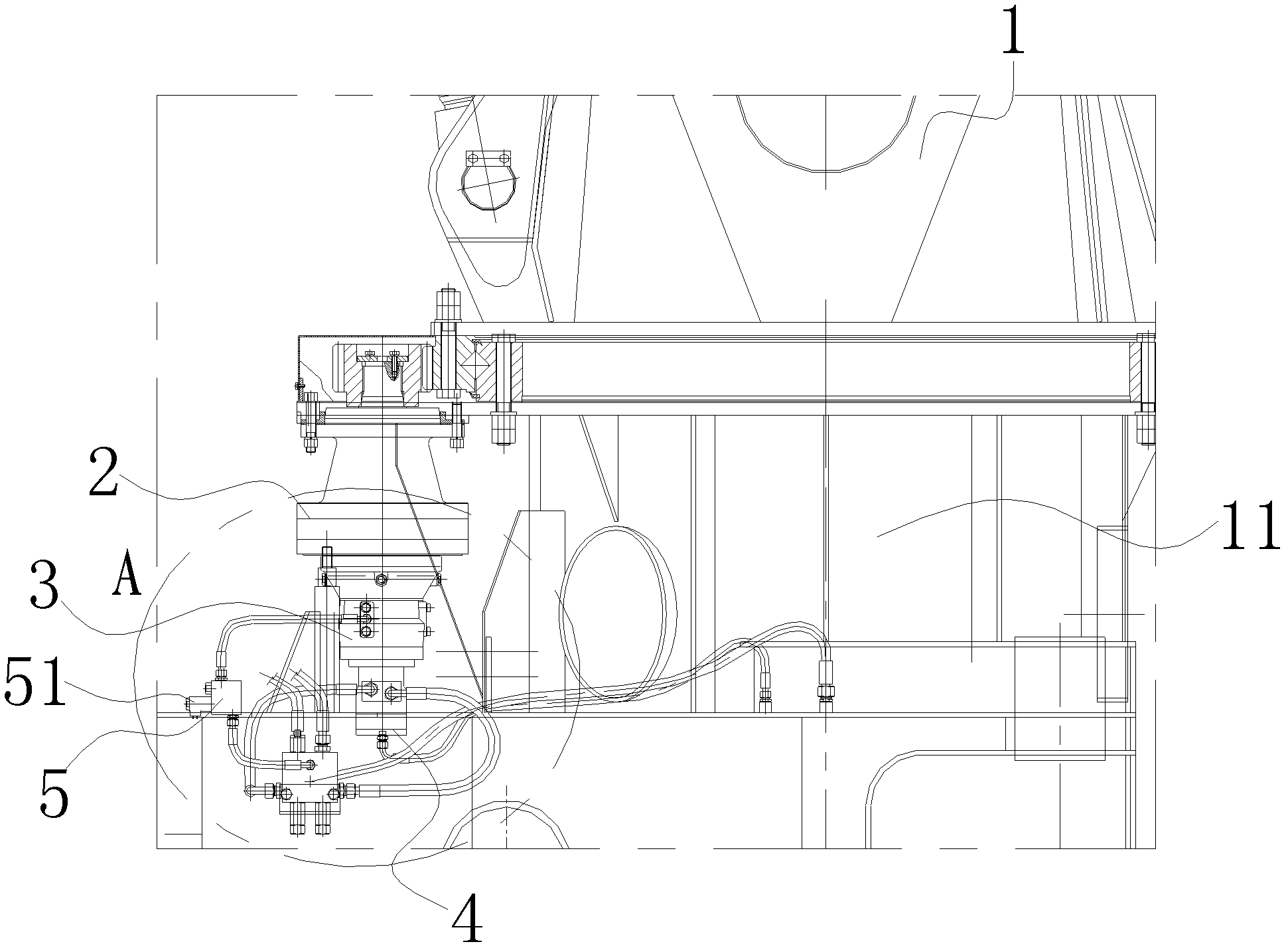
A technology of buffer control and turntable, which is applied in the direction of construction, building structure, and building material processing, etc. It can solve the problems of small effective volume of unlocking cylinder, difficult buffer time, and difficult safety, so as to eliminate shaking and vibration and reduce labor intensity , the effect of additional load reduction

Active Publication Date: 2014-08-06
河北雷萨重型工程机械有限责任公司
View PDF4 Cites 0 Cited by
  • Summary
  • Abstract
  • Description
  • Claims
  • Application Information

AI Technical Summary

Problems solved by technology

Because the effective volume 21 of the unlocking oil cylinder locked by the turntable brake is generally small, and the one-way throttle valve 20 is used for delay, it is difficult to obtain a long enough buffer time. When enough buffering can be obtained, the brake locking mechanism 11 of the turntable will act to lock the turntable 18, so that the end of the flexible long arm frame stretched tens of meters outside, the rotation has not stopped, but the turntable 18 has been braked and locked, resulting in tens of meters. The flexible long boom, under the action of both the inertial force of the movement and the rebound force of the structure, shakes and oscillates left and right in the air until the shaking oscillation fails and stops
This kind of large left and right shaking, measured from the end of the boom tens of meters away, has a swing range of up to 1.5M to 2M, which will cause huge structural damage. operation, bringing great difficulties and potential safety hazards

Method used


Image

  • Hydraulic rotary table parking buffer control equipment
  • Hydraulic rotary table parking buffer control equipment
  • Hydraulic rotary table parking buffer control equipment

Examples


Embodiment Construction

[0022] Embodiments of the present invention are described in detail below, examples of which are shown in the drawings, wherein the same or similar reference numerals designate the same or similar elements or elements having the same or similar functions throughout. The embodiments described below by referring to the figures are exemplary only for explaining the present invention and should not be construed as limiting the present invention.

[0023] In describing the present invention, it should be understood that the terms "center", "longitudinal", "transverse", "upper", "lower", "front", "rear", "left", "right", " The orientations or positional relationships indicated by "vertical", "horizontal", "top", "bottom", "inner", "outer", etc. are based on the orientation or positional relationships shown in the drawings, and are only for the convenience of describing the present invention and simplifying Describes, but does not indicate or imply that the device or element referred...


PUM


Abstract

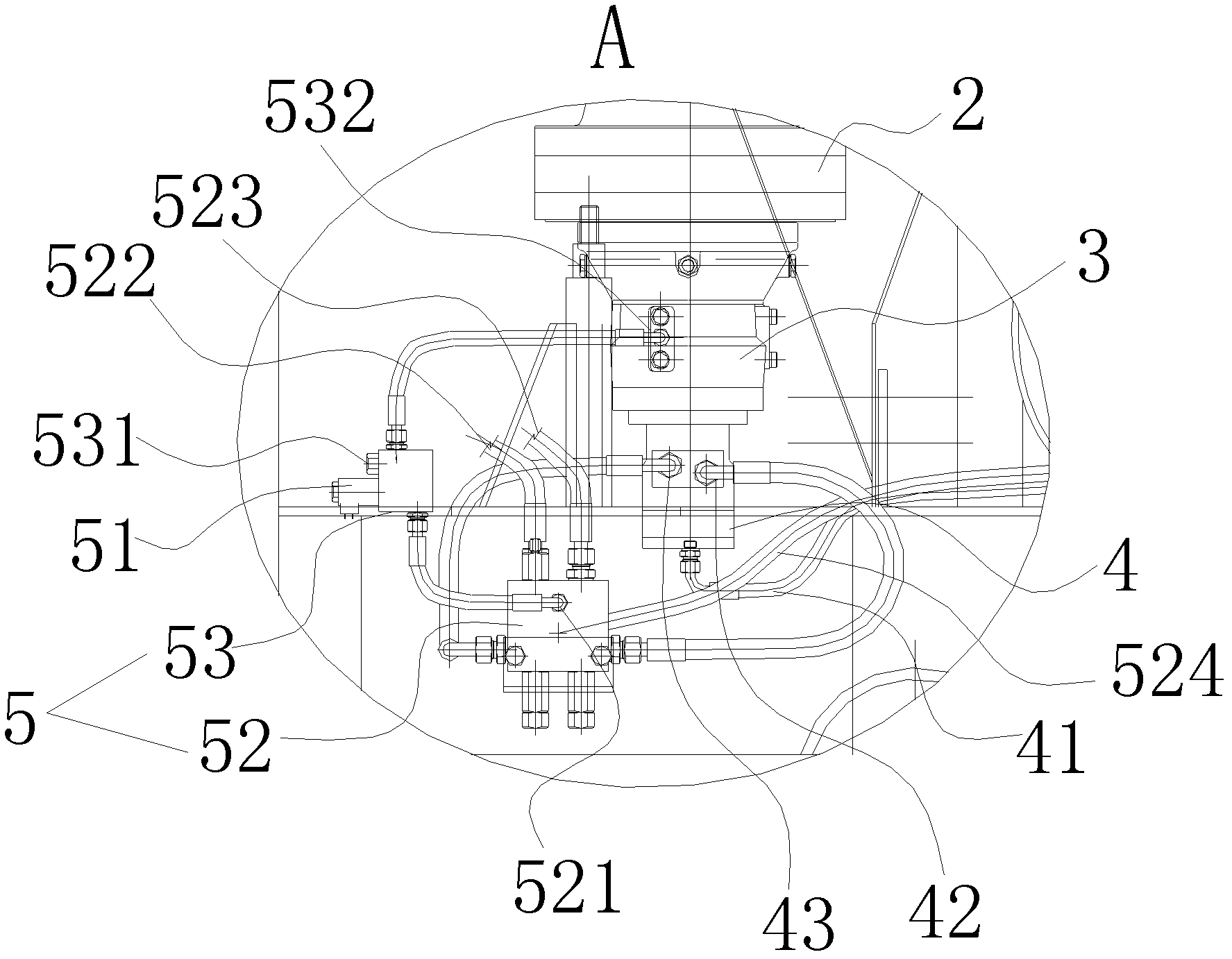
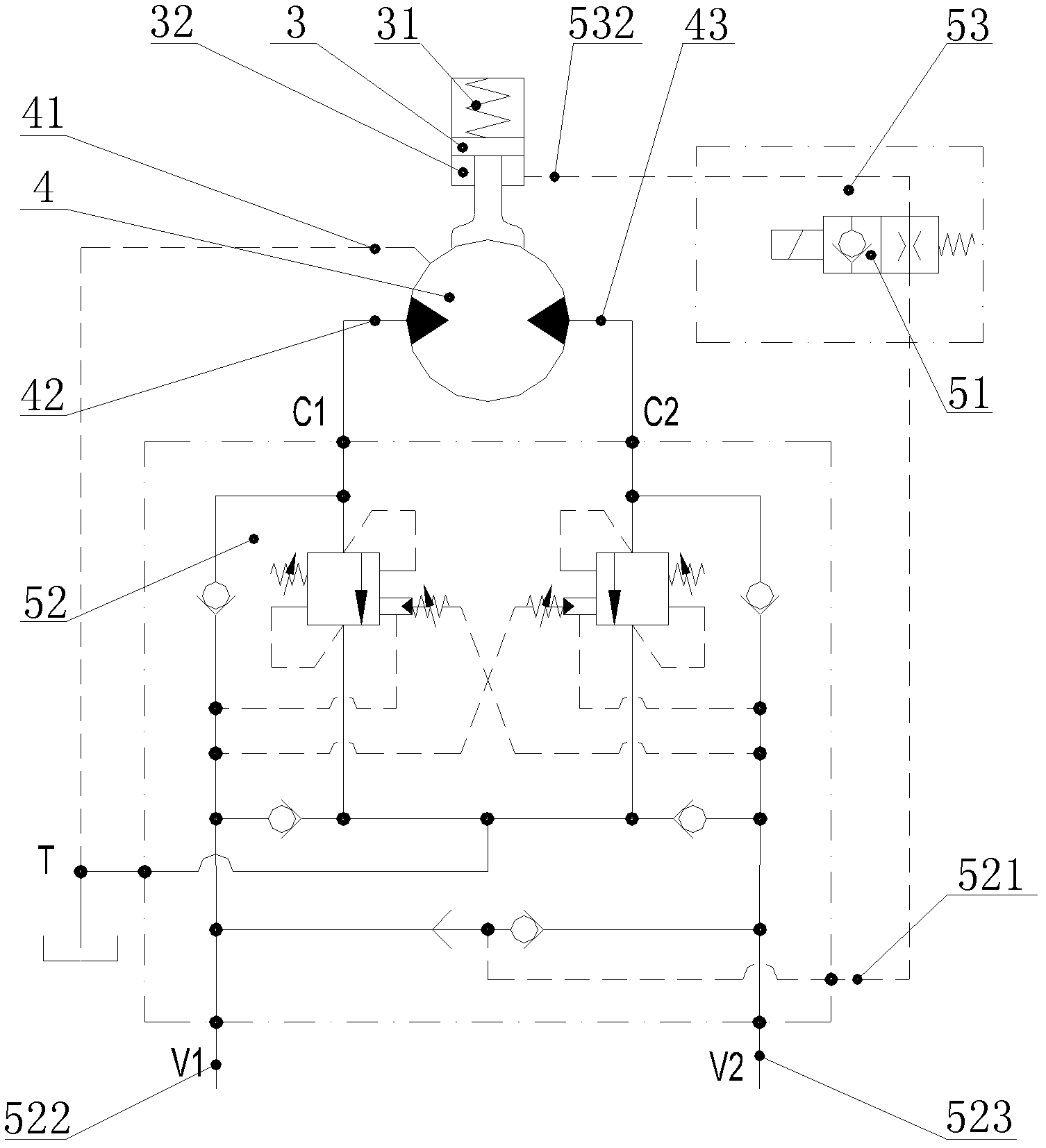
The invention discloses hydraulic rotary table parking buffer control equipment, which comprises a rotary table, a drive speed reducer, a speed reducer brake, a speed reducer hydraulic drive motor and a buffer control device, wherein the buffer control device is provided with a solenoid valve so as to be respectively connected with the speed reducer brake and the speed reducer hydraulic drive motor through the solenoid valve, so that the solenoid valve controls on-off of the speed reducer hydraulic drive motor so as to control delay brake time when the rotary table is stopped. According to the hydraulic rotary table parking buffer control equipment provided by the embodiment of the invention, the buffer control device is arranged, so that inertial energy produced when the rotary table is stopped can be consumed through driving the speed reducer hydraulic drive motor to rotate and matching with a buffer valve on a motor control loop to act, the parking stoppage of the rotary table is smooth, the related labor intensity is reduced, the service life of a machine is prolonged, and meanwhile, safety hazards caused by shaking and vibration of the rotary table are greatly eliminated.

Description

technical field [0001] The invention relates to the technical field of pump truck manufacturing, in particular, the invention relates to a parking buffer control device for a hydraulic turntable. Background technique [0002] The hydraulically driven turret with the characteristics of large moment of inertia will store huge rotational kinetic energy when it rotates. In order to realize the smooth start and parking of the turret, the existing technology is to install a hydraulic shock valve, which has two functions: A large inertia The hydraulic buffer when the turret starts to rotate realizes the rotation of the turret, which is slow to fast under the hydraulic drive until the turret obtains the required rotation speed, avoiding the impact of the hydraulic system; when the B moving large inertia turret stops , by adjusting the one-way throttle valve 20, the turntable can obtain a buffer delay time before the brake is locked, and its rotation can get a good parking buffer fro...

Claims


Application Information

Patent Timeline
Patent Type & Authority Patents(China)
IPC IPC(8): E04G21/04
Inventor 张戚蒋浩杨卫利魏严
Owner 河北雷萨重型工程机械有限责任公司
Learn More