

Fuel injection valve
A fuel injection valve, fuel injection technology, applied in the direction of fuel injection device, special fuel injection device, charging system, etc., can solve problems such as promoting combustion fluctuations
- Summary
- Abstract
- Description
- Claims
- Application Information
AI Technical Summary
Problems solved by technology
Method used
Image


Examples
Embodiment 1
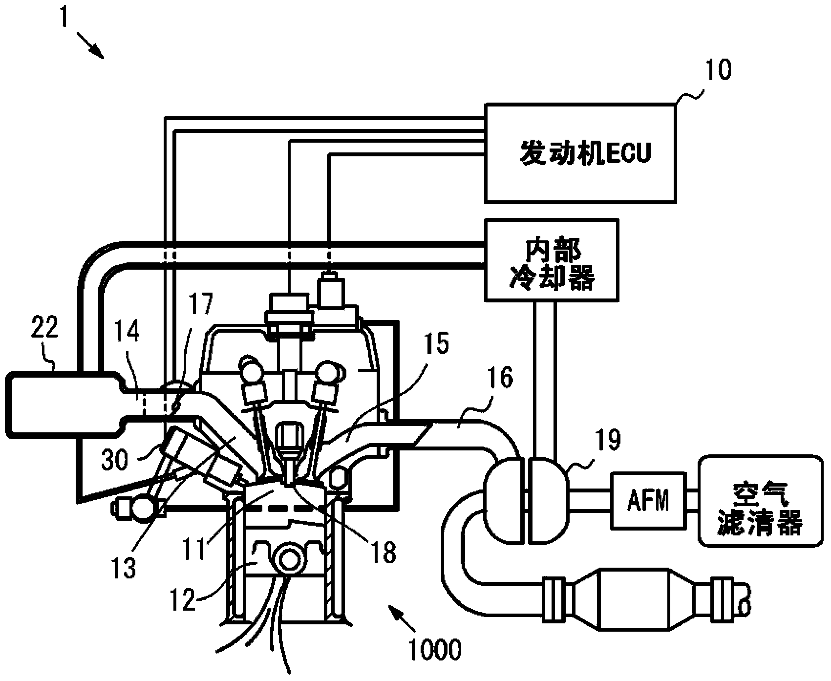
[0061] Embodiment 1 of the present invention will be described with reference to the drawings. figure 1 It is a diagram showing a configuration example of an engine system 1 equipped with a fuel injection valve 30 according to the present invention. In addition, in figure 1 Only a part of the structure of the engine 1000 is shown in the figure.
[0062] figure 1 The illustrated engine system 1 includes an engine 1000 as a power source, and an engine ECU (Electronic Control Unit: Electronic Control Unit) 10 for comprehensively controlling the operation of the engine 1000 . The engine system 1 includes a fuel injection valve 30 that injects fuel into the combustion chamber 11 of the engine 1000 . The engine ECU 10 has the function of a control unit. The engine ECU 10 is a computer including a CPU (Central Processing Unit: Central Processing Unit) for performing arithmetic processing, a ROM (Read Only Memory: Read Only Memory) for storing programs, etc., and a RAM (Random Acc...
Embodiment 2
[0088] Next, refer to Figure 9 to Figure 11 Example 2 will be described. Figure 9 It is an explanatory diagram showing enlarged the tip portion of the fuel injection valve 50 according to the second embodiment set in the valve closed state. Figure 10 This is an enlarged explanatory diagram showing the tip portion of the fuel injection valve 50 of the second embodiment in which the needle member 33 rises to expand the first gap portion 37 while maintaining the closed state of the injection hole 32 . Figure 11 It is an explanatory diagram showing enlarged the tip portion of the fuel injection valve 50 of the embodiment 2 set in the valve open state.
[0089] The difference between the fuel injection valve 50 of the second embodiment and the fuel injection valve 30 of the first embodiment is as follows. That is, the fuel injection valve 50 of the second embodiment includes a valve member 51 instead of the valve member 38 included in the fuel injection valve 30 . In additio...
Embodiment 3
[0094] Next, refer to Figure 12 The fuel injection valve 60 of the third embodiment will be described. Figure 12 This is an enlarged explanatory diagram showing the tip portion of the fuel injection valve of Example 3 in which the needle member 33 rises to expand the first clearance (suction chamber) 37 while maintaining the closed state of the injection hole 32 .
[0095] The points of difference between the fuel injection valve 60 of the third embodiment and the fuel injection valve 50 of the second embodiment are as follows. The fuel injection valve 60 is provided with an elastic member 61 instead of the elastic member 52 provided in the fuel injection valve 50 . Since the other structural elements of the fuel injection valve 60 are the same as those of the fuel injection valve 50, the same reference numerals are assigned to the common structural elements in the drawings, and detailed description thereof will be omitted.
[0096] The elastic member 52 is a coil-shaped s...
PUM
 Abstract
Description
Claims
Application Information