Interbody fusion apparatus

An intervertebral fusion device and intervertebral technology, applied in the field of intervertebral fusion devices, can solve the problems of strong foreign body sensation, low holding force between the intervertebral fusion device and adjacent vertebral blocks, and poor stability, so as to reduce the probability of dysphagia , protect the blood supply of the human body, and have high holding power

Inactive Publication Date: 2013-11-20
SHUANGYANG MEDICAL INSTR SUZHOU
View PDF8 Cites 10 Cited by
  • Summary
  • Abstract
  • Description
  • Claims
  • Application Information

AI Technical Summary

Problems solved by technology

The disadvantage of this kind of intervertebral fusion device is: the holding force between the intervertebral fusion device and the adjacent vertebral block is low, and the stability is poor, so a steel plate needs to be placed on one side of the intervertebral fusion device, and the two ends of the steel plate are connected to the vertebral body by screws respectively. Adjacent vertebral masses are immobilized by cages
This is not only cumbersome to operate, especially when the intervertebral disc of the human cervical spine needs to use the above-mentioned intervertebral fusion device, since there are esophagus and trachea in front of the cervical spine, placing a steel plate higher than the surface of the cervical spine in the anterior approach of the cervical spine is not only not conducive to the blood supply of the human body, Make people feel a strong foreign body sensation after surgery, and also increase the incidence of postoperative dysphagia

Method used


Image

  • Interbody fusion apparatus
  • Interbody fusion apparatus
  • Interbody fusion apparatus

Examples


Embodiment Construction

[0013] The present invention will be further described below in conjunction with the accompanying drawings and specific embodiments.

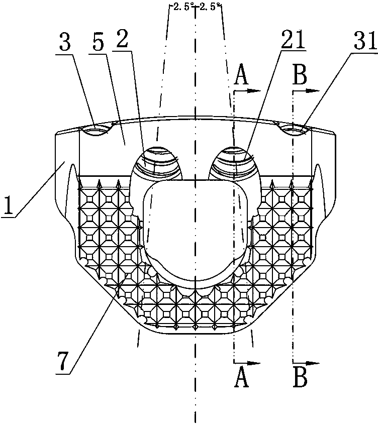
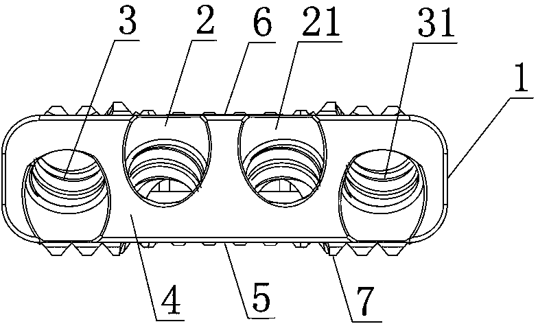
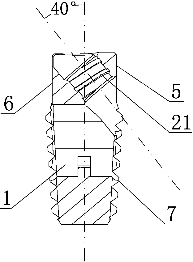
[0014] Such as figure 1 , figure 2 , image 3 , Figure 4 , Figure 5 As shown, the intervertebral fusion device includes an intervertebral fusion device body 1, and the upper and lower surfaces of the intervertebral fusion device body 1 are respectively inclined inwardly from front to back, and on the intervertebral fusion device body 1 At least two sets of intervertebral fusion locking holes are provided. In this embodiment, two sets of intervertebral fusion locking holes are opened on the intervertebral fusion device body 1, and each group of intervertebral fusion locking holes can pass through the intervertebral fusion device body 1. The upper locking screw hole and the lower locking screw hole are composed of the upper locking screw hole and the lower locking screw hole, that is, the two sets of intervertebral fusion locking screw hol...


PUM


Abstract

The invention discloses an interbody fusion apparatus. The interbody fusion apparatus comprises an interbody fusion apparatus body, both the upper surface and the lower surface of the interbody fusion apparatus body incline inwardly gradually from front to back, at least two interbody fusion locking hole groups are formed in the interbody fusion apparatus body, each interbody fusion locking hole group includes two locking screw holes penetrating the interbody fusion apparatus body, an inlet end and an outlet end of one of the locking screw holes in each interbody fusion locking hole group are formed on the front lateral face and the upper surface of the interbody fusion apparatus body respectively, an inlet end and an outlet end of the other locking screw hole are formed on the front lateral face and the lower surface of the interbody fusion apparatus body respectively, and an axis of each locking screw hole is ensured to form an included angle at 37-43 degrees with a horizontal section of the interbody fusion apparatus body and to form an included angle at 2-3 degrees with a vertical section of the interbody fusion apparatus body. The interbody fusion apparatus has the advantages that operation is simple, no incisura is generated, and people feel no foreign body after operation.

Description

technical field [0001] The invention relates to the field of medical instruments, in particular to an intervertebral fusion device used for fusion of spinal and vertebral bodies. Background technique [0002] When the intervertebral disc of the spine is diseased or necrotic, vertebral body fusion surgery is required. The traditional surgical plan is: remove the diseased intervertebral disc, and then place an intervertebral fusion cage in the same shape as the intervertebral disc at the removed intervertebral disc . The structure of the currently used intervertebral fusion includes a body of the intervertebral fusion. The disadvantage of this kind of intervertebral fusion device is: the holding force between the intervertebral fusion device and the adjacent vertebral block is low, and the stability is poor, so a steel plate needs to be placed on one side of the intervertebral fusion device, and the two ends of the steel plate are connected to the vertebral body by screws res...

Claims


Application Information

Patent Timeline
Patent Type & Authority Applications(China)
IPC IPC(8): A61F2/44
CPCA61F2/44A61F2002/30001
Inventor 钱建清
Owner SHUANGYANG MEDICAL INSTR SUZHOU
Why Eureka
Try Eureka