Noise eliminating method and noise eliminating circuit

A technology of noise cancellation, power stage circuit, applied in the field of electronics, can solve problems such as increased circuit loss

Active Publication Date: 2013-11-20
SILERGY SEMICON TECH (HANGZHOU) CO LTD
View PDF5 Cites 12 Cited by
  • Summary
  • Abstract
  • Description
  • Claims
  • Application Information

AI Technical Summary

Problems solved by technology

[0006] The technical solution in the prior art is to eliminate noise by adding a dummy loa

Method used


Image

  • Noise eliminating method and noise eliminating circuit
  • Noise eliminating method and noise eliminating circuit
  • Noise eliminating method and noise eliminating circuit

Examples


Embodiment 1

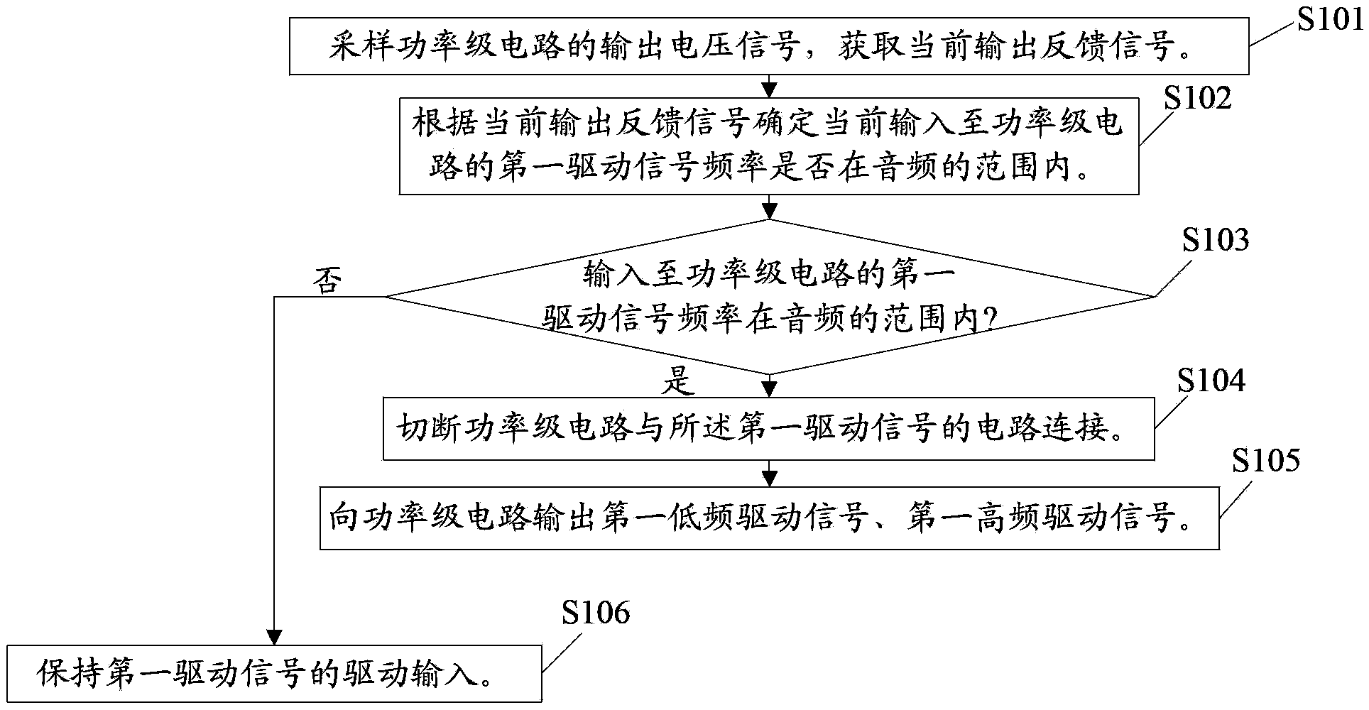
[0158] see figure 1 As shown, the present embodiment provides a noise elimination method, which mainly includes the following steps:

[0159] Step S101: Sampling the output voltage signal of the power stage circuit to obtain the current output feedback signal.

[0160] At the output end of the power stage circuit, the output voltage signal is sampled by the sampling feedback circuit 202, and the current output feedback signal is obtained by the sampling feedback circuit 202, and the output feedback signal changes with the change of the current output voltage signal. for example:

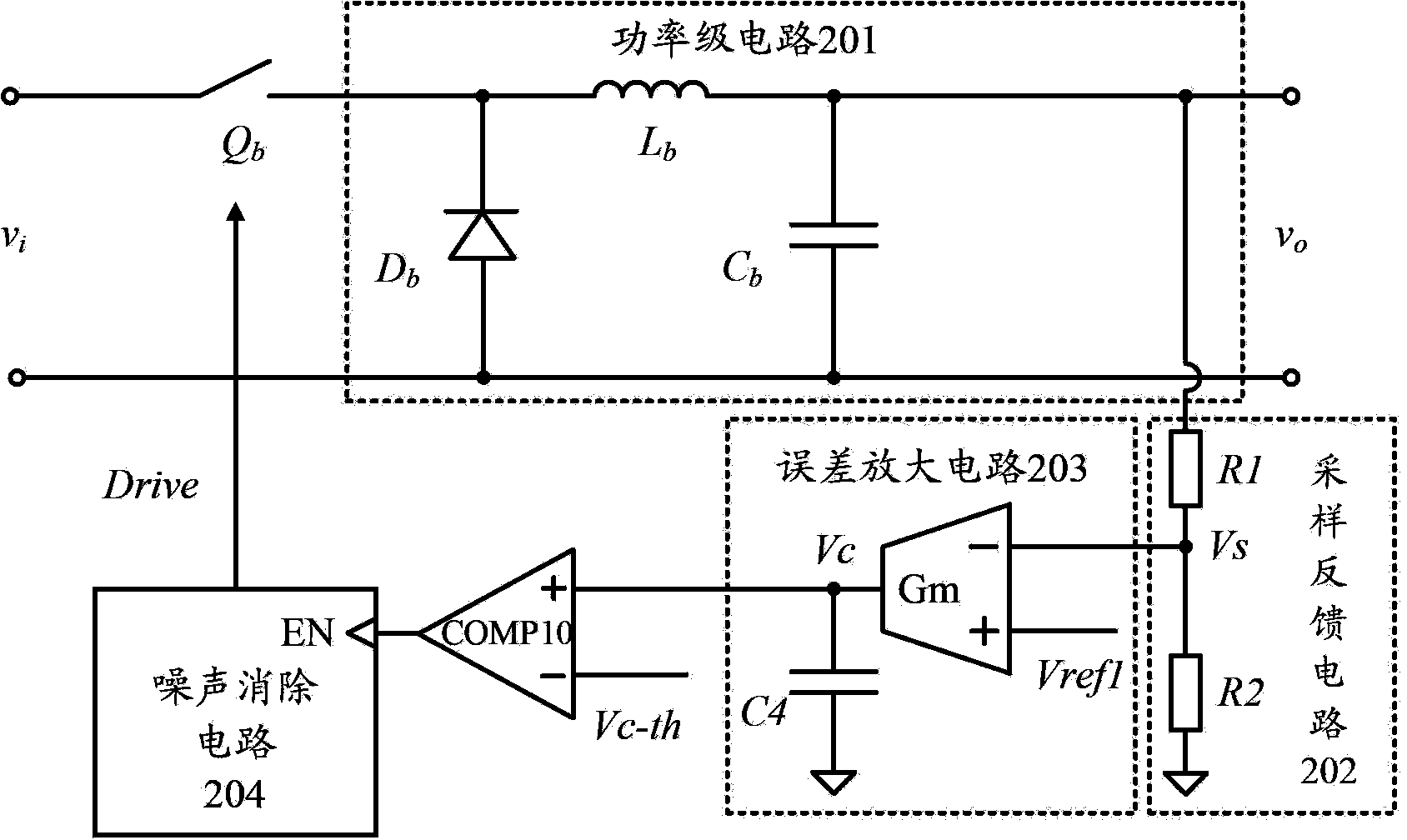
[0161] figure 2 The sampling circuit is connected to the output terminal of the power stage circuit as the sampling feedback circuit 202 through a resistance voltage dividing sampling circuit to obtain an output feedback signal Vs, and the output feedback signal Vs is proportional to the output voltage signal Vo, Vs=Vo*R2 / (R1+R2 ).

[0162] Step S102: Determine whether the frequency of the first...

Embodiment 2

[0185] The only difference between this embodiment and embodiment 1 is:

[0186] As an illustration of this embodiment, the first low-frequency drive signal f_Lq that is input to the power stage circuit and is lower than the audio frequency lower limit can be obtained, but not limited to, using the following technical solutions, which mainly include the following steps:

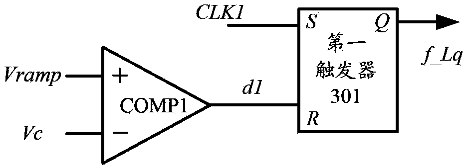
[0187] Step S1051: Comparing the output feedback error signal with the low-frequency reference ramp voltage, and outputting a first-level signal whose frequency is lower than the audio frequency lower limit.

[0188] In this embodiment, the low-frequency reference ramp voltage can be predetermined as: the output feedback voltage when the frequency of the driving signal of the power stage circuit is a preset frequency lower than the audio frequency lower limit, denoted as Vramp. For example, but not limited to, the corresponding output voltage signal when the driving frequency is 10 Hz can be set as the low-fr...

Embodiment 3

[0197] The only difference between this embodiment and embodiment 1 is:

[0198] As an illustration of this embodiment, the first high-frequency driving signal f_Hq higher than the upper audio frequency limit input to the power stage circuit may be implemented by, but not limited to, a hysteresis method. Obtaining the first high-frequency drive signal f_Hq according to the hysteresis method The technical solution mainly includes the following steps:

[0199] Step S301: Compare the current output feedback signal with the first low-frequency output feedback lower limit, and output a first comparison signal f1.

[0200] Wherein, the first low-frequency output feedback lower limit is preset as a minimum value that can represent the output feedback signal.

[0201] The lower limit of the first low frequency output feedback can be set as, but not limited to: when the frequency of the drive signal of the power stage circuit is lower than the first low frequency of the audio frequenc...


PUM


Abstract

The invention relates to the field of electronics and discloses a noise eliminating method and a noise eliminating circuit. The noise eliminating method comprises the following steps of sampling output voltage signals of a power-level circuit, and obtaining a current output feedback signal; and determining whether the frequency of a first driving signal currently input to the power-level circuit is in an audio range according to a current output feedback signal, if yes, disconnecting the power-level circuit and a circuit of the first driving signal, outputting a first low-frequency driving signal and a first high-frequency driving signal to the power-level circuit, wherein the frequency of the first low-frequency driving signal is lower than the lower limit of the audio, and the frequency of the first high-frequency driving signal is higher than the upper limit of the audio. The application of the technical scheme of the invention facilitates the reduction of the circuit noise and avoidance of the circuit loss.

Description

technical field [0001] The invention relates to the field of electronics, in particular to a noise elimination method and a noise elimination circuit. Background technique [0002] The power supply is generally composed of a power stage circuit and a control circuit. When the power stage circuit is in a light-load working state, the output feedback signal detected by the control circuit representing the output voltage will decrease. In the control circuit, a threshold is generally set to represent the light-load state of the load. When the output feedback signal is lower than the threshold, the power stage circuit enters the light-load working state, that is, the burst mode. At this time, the control circuit will work intermittently, that is, the frequency of the driving signal input to the power stage circuit will decrease, and as the load becomes lighter, the frequency of the driving signal will also decrease. [0003] In the circuit, when the frequency of the driving sig...

Claims


Application Information

Patent Timeline
IPC IPC(8): H02M1/14H02M1/12
Inventor 曹何金生余峰
Owner SILERGY SEMICON TECH (HANGZHOU) CO LTD
Why Eureka
Try Eureka