Tuner

A tuner and frequency mixing technology, which is applied in the field of tuners, can solve problems such as leakage of mixed frequency signals at the antenna end, and achieve the effect of reducing audio noise

Inactive Publication Date: 2012-05-09
SEMICON COMPONENTS IND LLC
View PDF5 Cites 0 Cited by
  • Summary
  • Abstract
  • Description
  • Claims
  • Application Information

AI Technical Summary

Problems solved by technology

[0006] In addition, if Figure 5 As shown, when a mixer is used, there will be a phenomenon that the mixed signal (local oscillator signal) leaks at the antenna end

Method used


Image

  • Tuner
  • Tuner
  • Tuner

Examples


Embodiment Construction

[0038] Embodiments of the present invention will be described below based on the drawings.

[0039] Figure 20 A partial structure of a radio set with a plurality of tuners is shown in . n tuners T1 to Tn are connected to the antenna ANT. The respective tuners T1 to Tn have the same configuration.

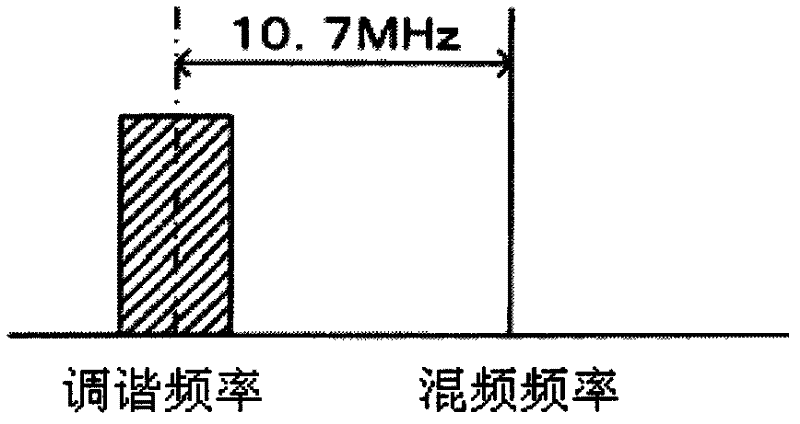
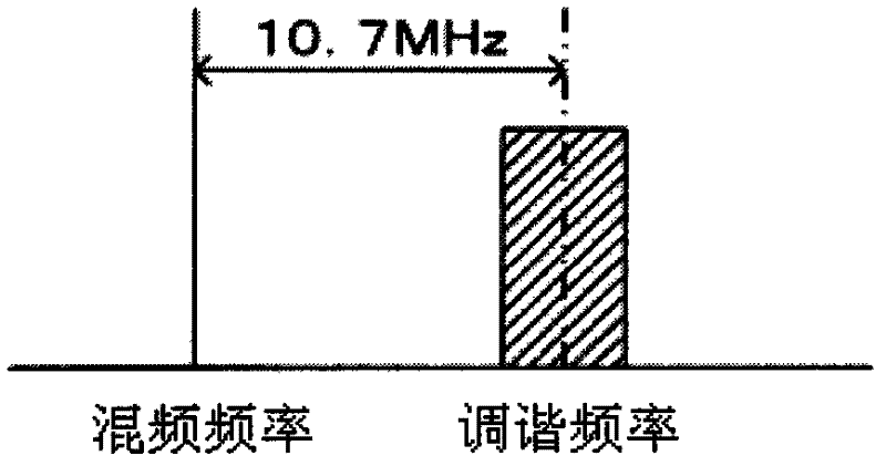
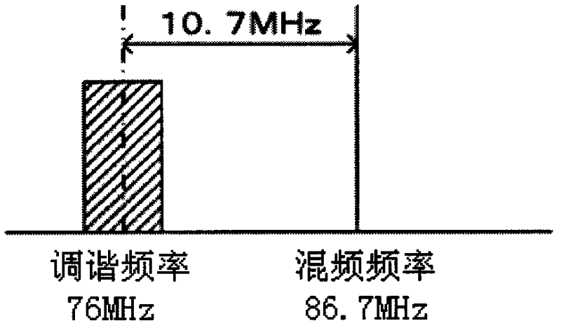
[0040] In a tuner, a received signal from an antenna ANT is input to an RF amplifying circuit 10, where RF amplification is performed, and the amplified received signal is input to a mixer 12, where it is mixed with a mixed signal from an oscillator 14. Frequency signal mixing. Here, the oscillation frequency of the oscillator 14 is controlled by the control unit 16 to control the frequency of the mixing signal of the oscillator 14 . The control unit 16 is supplied with a selection signal of a broadcasting station, and the control unit 16 controls the oscillator to oscillate at a frequency deviated from the IF frequency of the selected broadcasting station.

[0041] The IF fil...


PUM


Abstract

Noise in an audio output is reduced even if a mixing signal leaks to another tuner. A broadcast wave is received from a broadcast station by an antenna to which a mixing signal is mixed by a mixer (12) to obtain an IF signal and demodulated by a demodulator (22). An oscillator (14) outputs a mixing signal having a frequency difference of at least a barely audible frequency within an audio frequency band from any broadcast station center frequency allocated at a predetermined frequency spacing, the mixing signal is mixed by the mixer (12) with the signal received by the antenna, and the IF signal is obtained.

Description

technical field [0001] The present invention relates to a tuner for receiving audio broadcasts such as FM (Frequency Modulation) radio and AM (Amplitude Modulation: Amplitude Modulation) radio. Background technique [0002] Conventionally, in an FM radio, an IF (Intermediate Frequency: intermediate frequency) frequency of a tuner for receiving broadcast waves is set to 10.7 MHz. Furthermore, the IF signal was extracted using a ceramic filter for IF filtering whose pass signal center frequency is 10.7 MHz. [0003] Here, when the IF frequency is set to 10.7 MHz, the RF (Radio frequency: radio frequency) mixing frequency (oscillation frequency of the local oscillator) is the tuning frequency ±10.7 MHz. figure 1 shows the frequency relationship of tuning frequency +10.7MHz, figure 2 The frequency relationship of tuning frequency - 10.7 MHz is shown in . [0004] For example, in the case of converting the tuning frequency 76MHz frequency to IF by setting up, as image 3 As ...

Claims


Application Information

Patent Timeline
Patent Type & Authority Applications(China)
IPC IPC(8): H04B1/10H04B1/16
CPCH04H40/18H04H2201/60
Inventor 栗原信二
Owner SEMICON COMPONENTS IND LLC
Why Eureka
Try Eureka