Drawing punch

A punch and end face technology, used in metal processing equipment, forming tools, manufacturing tools, etc., can solve problems such as tearing of metal parts and increase production costs, and achieve the effects of avoiding damage, reducing production costs, and alleviating impact.

Inactive Publication Date: 2013-11-27
TIANJIN HUASHUN AUTO PARTS MFR GRP
View PDF0 Cites 1 Cited by
  • Summary
  • Abstract
  • Description
  • Claims
  • Application Information

AI Technical Summary

Problems solved by technology

[0002] Metal parts are usually processed by stamping dies. Stretching is a common process for metal parts stamping. Because the impact force is very large during stamping, it is easy to tear the metal parts and increase the production cost.

Method used


Image

  • Drawing punch

Examples


Embodiment Construction

[0009] The present invention will be further described below by embodiment.

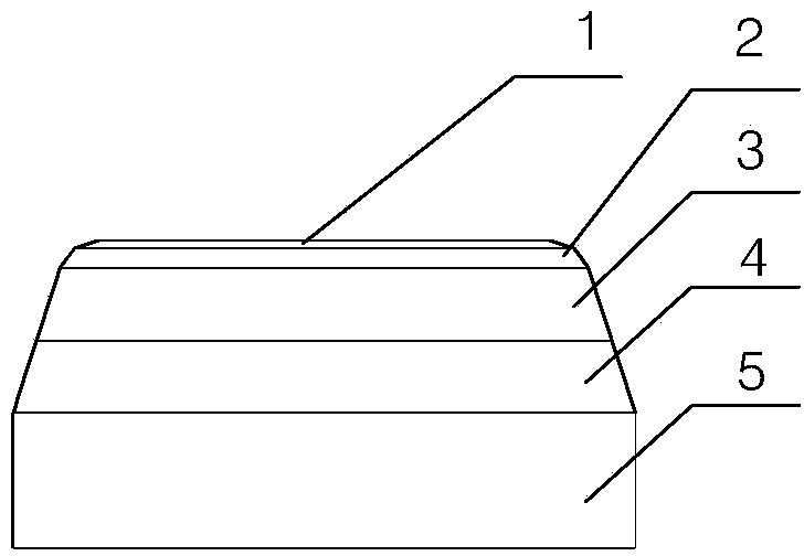
[0010] attached by figure 1 It can be seen that the present invention includes a punch base 5 and a punch end face 1, a transition stretching surface is provided between the punch base 5 and the punch end face 1, and the excessive stretching surface is formed by the third stretching Surface 4, the second stretching surface 3, and the first stretching surface 2 are formed, and indented and transitioned inwardly, wherein the indentation angle between the third stretching surface 4 and the vertical surface is 10-15°, and the second stretching surface The retraction angle between the stretching surface 3 and the vertical surface is 15-20°, and the retraction angle between the first stretching surface 2 and the vertical surface is 20-30°.

[0011] Due to the gradual transition of the stretching surface, when stretching the metal part, the direct impact of the punch on the metal part can be relieved, and ...


PUM


Abstract

The invention discloses a drawing punch, which relates to a stamping die and in particular relates to a punch of the stamping die. The drawing punch comprises a punch base and a punch end surface, wherein a transitional drawing surface is arranged between the punch base and the punch end surface, consists of a third drawing surface, a second drawing surface and a first drawing surface, and is retracted inwards for transition, an indentation angle between the third drawing surface and a vertical plane is 10-15 degrees, an indentation angle between the second drawing surface and the vertical plane is 15-20 degrees, and an indentation angle between the first drawing surface and the vertical plane is 20-30 degrees. The drawing punch has the beneficial effects that after a transitional stamping surface is adopted, the impact force applied to the punch can be effectively alleviated, the damage to a product caused by too high impact force of the punch can be avoided, and the production cost is reduced.

Description

technical field [0001] The invention relates to a stamping die, in particular to a punch of the stamping die. Background technique [0002] Stamping dies are commonly used for metal parts processing. Stretching is a common process for metal parts stamping. Because the impact force is very large during stamping, it is easy to tear the metal parts and increase the production cost. Contents of the invention [0003] In order to solve the above problems, the present invention provides a stretching punch, which can reduce the impact force during depressurization and avoid tearing of metal parts caused by excessive impact force. [0004] In order to achieve the above object, the technical scheme adopted in the present invention is: [0005] A stretching punch, characterized in that it includes a punch base and a punch end face, a transitional stretching surface is provided between the punch base and the punching end face, and the excessive stretching surface is formed by the fi...

Claims


Application Information

Patent Timeline
Patent Type & Authority Applications(China)
IPC IPC(8): B21D37/00
Inventor 刘勇刘兴全
Owner TIANJIN HUASHUN AUTO PARTS MFR GRP
Why Eureka
Try Eureka