
Channel structure for guaranteeing flow rate

A technology of flow channel and flow rate, which is applied in the field of product mold structure, can solve the problems of slow injection molding speed, bubbles, and easy mixing of air into materials, so as to achieve the effect of ensuring speed and quality

Inactive Publication Date: 2013-11-27
WUXI CITY NEW DISTRICT WEICHUANGLI MOLD FACTORY
View PDF0 Cites 0 Cited by
  • Summary
  • Abstract
  • Description
  • Claims
  • Application Information

AI Technical Summary

Problems solved by technology

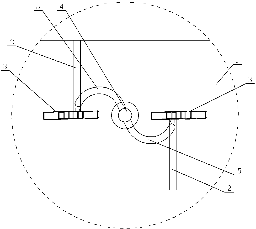
[0002] In the existing one-mold double-cavity structure of the mold, the runners have vertical runners leading into the horizontal transverse runners and then connected to the horizontal longitudinal runners through a right-angle turn, and the horizontal longitudinal runners are connected to the corresponding cavities. There is a right-angle turn in the plane, which reduces the flow rate of the material in the flow channel, which in turn slows down the injection molding rate, and after the flow rate slows down, air is easy to mix into the material, causing air bubbles inside the injection molded product, which affects the quality of the injection molded product

Method used


Image

  • Channel structure for guaranteeing flow rate

Examples


Embodiment Construction

[0007] See figure 1 , which includes a front mold 1, a rear mold (not shown in the figure, which belongs to the existing mature structure), an insert 2, two cavities 3 between the front mold 1, the rear mold, and the insert 2, and a vertical flow channel 4 The lower part of the horizontal flow channel is connected to the horizontal flow channel, and the horizontal flow channel is specifically an arc-shaped flow channel 5. The lower part of the vertical flow channel 4 is respectively connected to the inlets of the circular-arc-shaped flow channels 5 on both sides, and the outlet of the arc-shaped flow channel 5 is connected to the corresponding Cavity 3.


PUM


Abstract

The invention provides a channel structure for guaranteeing a flow rate. Through the channel structure, after the liquid enters into horizontal channels from a vertical channel, a flow rate is not influenced, an injection molding rate is guaranteed, mixing of air and a material is avoided and injection molding product quality is guaranteed. The channel structure comprises a front mold, a rear mold and inserts. Two cavities are formed among the front mold, the rear mold and the inserts. The lower part of the vertical channel is communicated with the horizontal channels. The channel structure is characterized in that the horizontal channels are circular channels; the lower part of the vertical channel is communicated respectively with inlets of the circular channels at two sides of the lower part of the vertical channel; and outlets of the circular channels are communicated respectively with the cavities.

Description

technical field [0001] The invention relates to the structural technical field of product moulds, in particular to a flow channel structure for ensuring flow velocity. Background technique [0002] In the existing one-mold double-cavity structure of the mold, the runners have vertical runners leading into the horizontal transverse runners and then connected to the horizontal longitudinal runners through a right-angle turn, and the horizontal longitudinal runners are connected to the corresponding cavities. There is a right-angle turn in the plane, which reduces the flow rate of the material in the flow channel, which in turn slows down the injection molding rate, and after the flow rate slows down, air is easy to mix into the material, causing air bubbles inside the injection-molded product, which affects the quality of the injection-molded product. Contents of the invention [0003] The invention provides a flow cha...

Claims


Application Information

Patent Timeline
Patent Type & Authority Applications(China)
IPC IPC(8): B29C45/27B29C45/32
Inventor 吕应军
Owner WUXI CITY NEW DISTRICT WEICHUANGLI MOLD FACTORY
Learn More