Same-tower double-power transmission circuit single-end traveling wave fault location method

A technology of double circuits and transmission lines on the same tower, applied in directions such as fault locations, can solve problems such as incorrect ranging results and excessive equipment investment.

Active Publication Date: 2013-11-27
KUNMING UNIV OF SCI & TECH
View PDF6 Cites 14 Cited by
  • Summary
  • Abstract
  • Description
  • Claims
  • Application Information

AI Technical Summary

Problems solved by technology

The double-ended traveling wave ranging method requires a lot of equipment investment, requires synchronous data acquisition, and requires data exchange and communication. Although the traditional single-ended traveling wave ranging method is ...

Method used


Image

  • Same-tower double-power transmission circuit single-end traveling wave fault location method
  • Same-tower double-power transmission circuit single-end traveling wave fault location method
  • Same-tower double-power transmission circuit single-end traveling wave fault location method

Examples


Embodiment 1

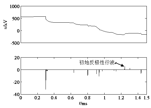
[0052] Example 1: Phase A metallic grounding fault occurs at a distance of 50km from the measurement terminal M of the I circuit line of the double-circuit transmission line on the same tower. The measurement terminal M detects and records the traveling wave data 1.5ms after the fault, the fault voltage traveling wave and its wavelet Transform modulus maxima such as image 3 shown.

[0053] 1. According to the step (2) of claim 2, take the arrival time of the initial traveling wave of the fault as the reference time, and calculate the distance reflected by the waves of the same polarity:

[0054] =[50.36, 74.65, 89.70, 94.62, 100.87, 115.18, 121.29, 125.16] km;

[0055] Similarly, taking the arrival time of the initial anti-polarity traveling wave as the reference time, calculate the distance reflected by the head of each same-polarity traveling wave:

[0056] =[89.85, 65.56, 50.51, 45.59, 39.34, 25.03, 18.92, 15.05] km.

[0057] 2. According to the claim step (3), find...

Embodiment 2

[0063] Example 2: Phase A metallic grounding fault occurs at a distance of 90km from the measurement end M of the I circuit line of the double-circuit transmission line on the same tower. The measurement end M detects and records the traveling wave data of 1.5ms after the fault, the fault voltage traveling wave and its wavelet Transform modulus maxima such as Figure 5 shown.

[0064] 1. According to the step (2) of claim 2, take the arrival time of the initial traveling wave of the fault as the reference time, and calculate the distance reflected by the waves of the same polarity:

[0065] =[50.16, 74.64, 90.14, 94.76, 100.27, 115.03, 121.29, 124.71]km;

[0066] Similarly, taking the arrival time of the initial anti-polarity traveling wave as the reference time, calculate the distance reflected by the head of each same-polarity traveling wave:

[0067] =[90.18, 65.56, 50.06, 45.44, 39.93, 25.18, 18.92, 15.49]km.


PUM


Abstract

The invention provides a same-tower double-power transmission circuit single-end traveling wave fault location method, and belongs to the technical field of relay protection of electrical power systems. When a fault occurs to a same-tower double-power transmission circuit, voltage traveling wave data of each phase are detected and recorded; a voltage traveling wave mode maximum value of a fault phase is obtained by converting small waves, and distribution of a traveling wave head on a time axis is obtained; an initial reversed-polarity traveling wave head is marked, and a moment corresponding to the initial reversed-polarity traveling wave head is used as a referential moment to calculate the distance reflected by a same-polarity traveling wave head between an initial fault traveling wave head and the initial reversed-polarity traveling wave head; meanwhile, the moment when the initial fault traveling wave head arrives is used as a referential moment to calculate the distance reflected by the same-polarity traveling wave head between the initial fault traveling wave head and the initial reversed-polarity traveling wave head; two pairs of distances which are close or equal are found from the two sets of distances, and then the distance really reflecting the fault position is distinguished out through a simulation method after measurement.

Description

technical field [0001] The invention relates to a single-end traveling wave fault distance measurement method of a double-circuit transmission line on the same tower that does not rely on wave head identification, and belongs to the technical field of electric power system relay protection. Background technique [0002] The double-circuit transmission line on the same tower has been widely used because of its low engineering cost, small occupied corridor width, short construction period, simple operation and maintenance, and significant economic benefits. Accurate fault when double circuit fault [0003] The distance measurement method is of great practical significance to quickly and accurately find the fault point, quickly eliminate the fault and restore the power supply of the line in time. [0004] Fault location by traveling wave method for double-circuit transmission lines on the same tower is nothing more than single-ended method and double-ended method. The double-...

Claims


Application Information

Patent Timeline
IPC IPC(8): G01R31/08
Inventor 束洪春田开庆张兰兰
Owner KUNMING UNIV OF SCI & TECH
Why Eureka
Try Eureka