A Three-terminal Asynchronous Fault Location Method Based on the Distribution Characteristics of Fault Traveling Waves on T-connection Lines

A fault traveling wave and line connection technology, applied in the fault location, detecting faults by conductor type, measuring electricity and other directions, can solve problems such as three-terminal data synchronization, and achieve the effect of simple principle and accurate and reliable ranging results.

Active Publication Date: 2019-02-19
KUNMING UNIV OF SCI & TECH
View PDF11 Cites 0 Cited by
  • Summary
  • Abstract
  • Description
  • Claims
  • Application Information

AI Technical Summary

Problems solved by technology

[0004] The purpose of the present invention is to overcome the limitation that traditional T-connection transmission line fault distance measurement requires three-terminal data synchronization, and propose a method for distance measurement of T-connection line three-terminal asynchronous fault based on the distribution characteristics of fault traveling waves along the line

Method used


Image

  • A Three-terminal Asynchronous Fault Location Method Based on the Distribution Characteristics of Fault Traveling Waves on T-connection Lines
  • A Three-terminal Asynchronous Fault Location Method Based on the Distribution Characteristics of Fault Traveling Waves on T-connection Lines
  • A Three-terminal Asynchronous Fault Location Method Based on the Distribution Characteristics of Fault Traveling Waves on T-connection Lines

Examples


Embodiment 1

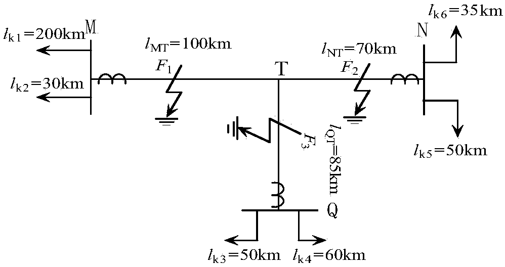
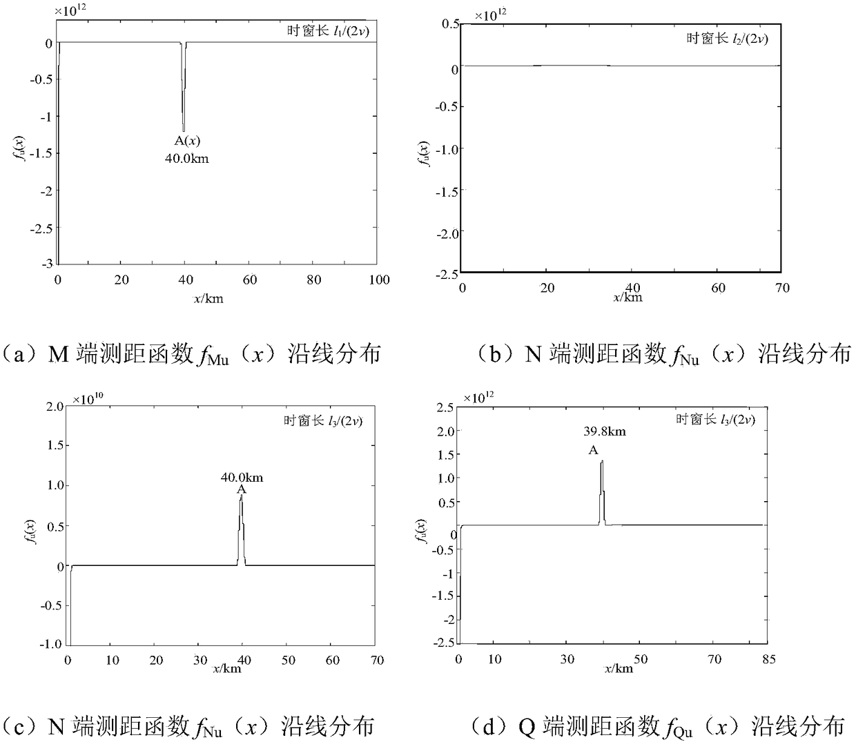
[0045] Embodiment 1: as figure 1 T is connected to the line shown, respectively by the line l MT , l NT and l QT Composition, where l MT = 100km, l NT =70km, l QT =85km. The M, N and Q terminals of the three-terminal busbars of the T-connection transmission line are multi-outlet busbars, and the three terminals are equipped with traveling wave distance measuring devices. When the MT branch is 40km away from the M terminal, a phase A ground fault occurs. At terminal M, the window length is l 1 / (2v)=0.168ms, ranging function f Mu (x) in l 1 The distribution results in the line length range are as follows figure 2 As shown in (a); at the N terminal, the window length is l 2 / (2v)=0.118ms, ranging function f Nu (x) in l 2 The distribution results in the line length range are as follows figure 2 As shown in (b); at the Q terminal, the window length is l 3 / (2v)=0.142ms, ranging function f Qu (x) in l 3 The distribution results in the line length range are as fol...

Embodiment 2

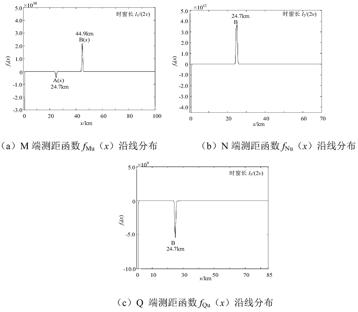
[0048] Such as figure 1 T is connected to the line shown, respectively by the line l MT , l NT and l QT Composition, where l MT = 100km, l NT =70km, l QT =85km. The M, N and Q terminals of the three-terminal busbars of the T-connection transmission line are multi-outlet busbars, and the three terminals are equipped with traveling wave distance measuring devices. When the NT branch is 25km away from the T node, a phase A ground fault occurs, respectively at the M, N and Q terminals, and the time windows are [t 0 ,t 0 +l 1 / (2v)], [t 0 ,t 0 +l 2 / (2v)] and [t 0 ,t 0 +l 3 / (2v)], ranging function f u (x) along the line l 1 , l 2 and l 3 The result is as image 3 shown.

[0049] Depend on image 3 It can be seen that the ranging function f of the M, N and Q terminals Mu (x), f Nu (x) and f Qu (x) two by two "and" logic shows that sgn(x M )&sgn(x N )=0, sgn(x M )&sgn(x Q )=1, and sgn(x N )&sgn(x Q )=0, it can be seen that the fault is located in the NT...

Embodiment 3

[0051] Such as figure 1 T is connected to the line shown, respectively by the line l MT , l NT and l QT Composition, where l MT = 100km, l NT =70km, l QT =85km. The M, N and Q terminals of the three-terminal busbars of the T-connection transmission line are multi-outlet busbars, and the three terminals are equipped with traveling wave distance measuring devices. When the QT branch is 20km away from the T node, a phase A ground fault occurs, respectively at the M, N and Q terminals, and the time windows are [t 0 ,t 0 +l 1 / (2v)], [t 0 ,t 0 +l 2 / (2v)] and [t 0 ,t 0 +l 3 / (2v)], ranging function f u (x) along the line l 1 , l 2 and l 3 The result is as Figure 4 shown.

[0052] Depend on Figure 4 It can be seen that the ranging function f of the M, N and Q terminals Mu (x), f Nu (x) and f Qu (x) two by two "and" logic shows that sgn(x M )&sgn(x N )=1, sgn(x M )&sgn(x Q )=0, and sgn(x N )&sgn(x Q )=0, it can be seen that the fault is located in the ...


PUM


Abstract

The invention relates to a fault location method for a T-connection line with three asynchronous terminals on the basis of distribution characteristics along a fault traveling wave and belongs to the technical field of relay protection of an electrical power system. When a fault occurs at a T-connection electric transmission line whose three terminals are all provided with traveling wave location devices, the three terminals are observed, a voltage distribution along the line and a current distribution along the line are calculated on fault traveling data obtained by a measuring terminal at a short time window; on the basis of the obtained voltage distribution along the line and current distribution along the line, and wave impedance, a direction traveling wave distributed along the line is obtained through resolving a traveling wave along the line; a location function is constructed by use of a forward traveling wave and a backward traveling wave; finally, fault location of the T-connection electric transmission line is realized on the basis of location function distribution rules of the three terminals. By use of the method, fault location for T-connection electric transmission line is realized; the principle of the method is simple; the method is independent of data synchronization of three terminals and is not influenced by factors such as fault instantaneity and fault transition resistance variation; the location results are accurate and reliable.

Description

technical field [0001] The invention relates to a three-terminal asynchronous fault ranging method of a T-connection line based on the distribution characteristics of fault traveling waves along the line, and belongs to the technical field of electric power system relay protection. Background technique [0002] In the power system, the T-connection line generally has the characteristics of large transmission power and heavy load. Once the line fails, it may cause a large-scale power outage. Therefore, when the T-connection line fails, quickly and accurately locate the fault point of the T-connection line, which can not only reduce the difficulty and workload of electrical maintenance personnel in troubleshooting, shorten the power outage time caused by the fault, and improve the reliability of power supply , and will generate huge economic and social benefits for the power production sector. [0003] Fault location methods are divided into impedance method, fault analysis m...

Claims


Application Information

Patent Timeline
Patent Type & Authority Patents(China)
IPC IPC(8): G01R31/08
CPCG01R31/085G01R31/088Y04S10/52
Inventor 束洪春余多田鑫萃
Owner KUNMING UNIV OF SCI & TECH
Why Eureka
Try Eureka