A single-ended traveling wave ranging method for double-circuit DC lines on the same tower based on energy mutation along the line

A technology of double-circuit and DC lines on the same tower, applied in the measurement of electrical variables, measurement of electricity, measurement devices, etc., can solve the problem of high requirements for accurate clock synchronization, and achieve the effect of accurate and reliable ranging results and simple principles.

Active Publication Date: 2019-04-12
KUNMING UNIV OF SCI & TECH
View PDF5 Cites 0 Cited by
  • Summary
  • Abstract
  • Description
  • Claims
  • Application Information

AI Technical Summary

Problems solved by technology

Among them, time-domain single-ended traveling wave ranging requires further research on the reliability of traveling wave head calibration and wave head identification, and the automation of ranging analysis; time-domain double-ended traveling wave Wave arrival time difference, the reliability and accuracy of the initial traveling wave calibration can be easily guaranteed, and there is no need to identify the reflected wave at the fault point, but the double-ended traveling wave ranging requires high precision synchronization of clocks at both ends of the line

Method used


Image

  • A single-ended traveling wave ranging method for double-circuit DC lines on the same tower based on energy mutation along the line
  • A single-ended traveling wave ranging method for double-circuit DC lines on the same tower based on energy mutation along the line
  • A single-ended traveling wave ranging method for double-circuit DC lines on the same tower based on energy mutation along the line

Examples


Embodiment 1

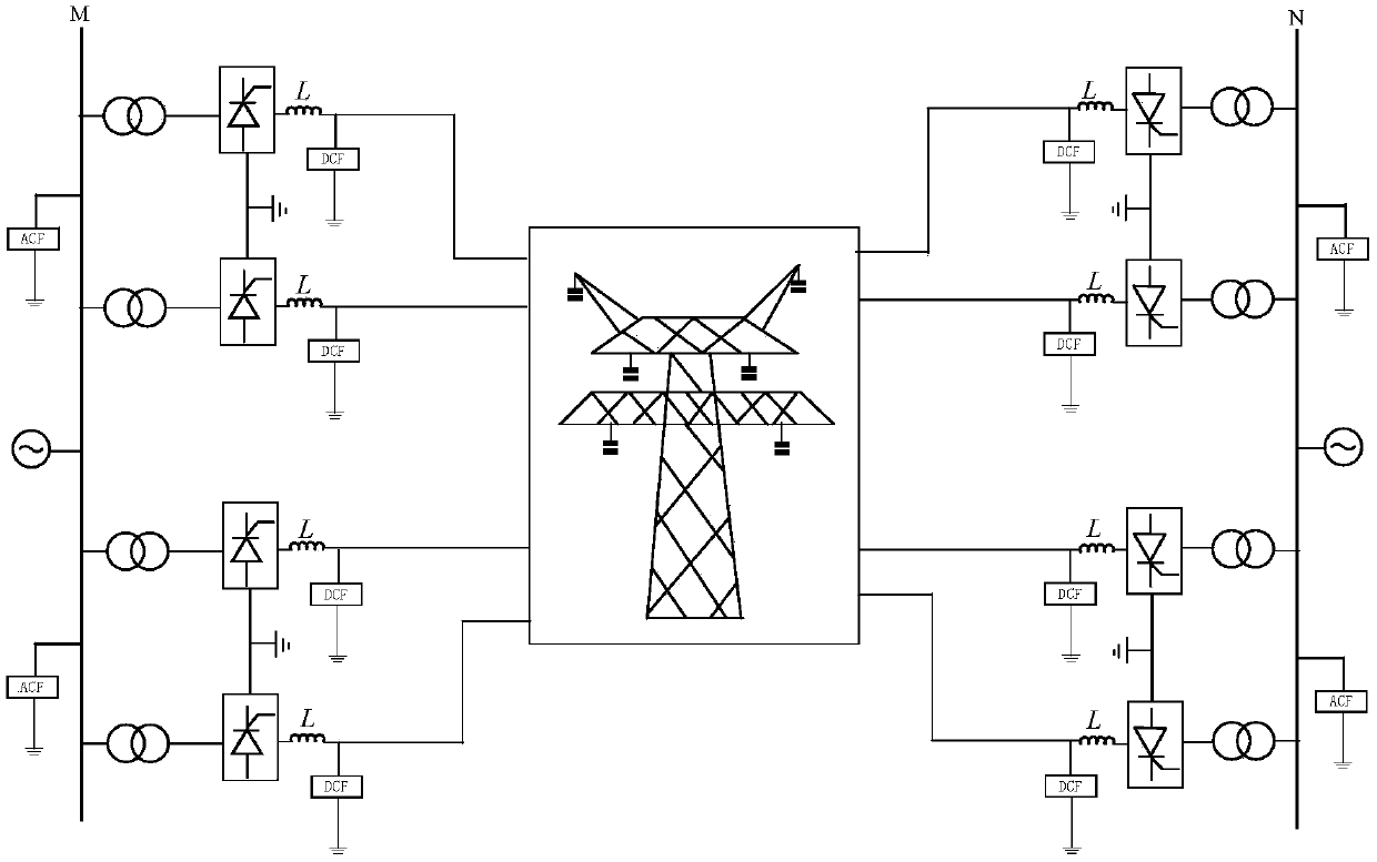
[0062] Embodiment 1: adopt as figure 1 The shown ±500kV double-circuit DC transmission system on the same tower. The total length of the line is 1286km. Four-split conductors are used. 0.3H smoothing reactors are installed on both sides of the line. Each pole is connected with a single 12-pulse valve group. The rated transmission power is 6400MW and the rated current is 3200A. The sampling rate is set to 1MHz.

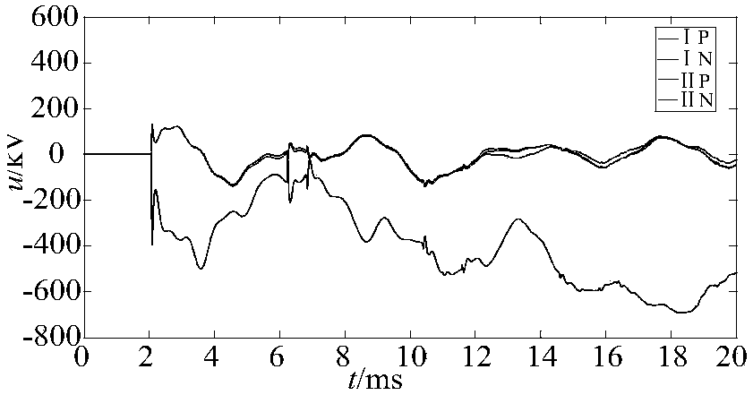
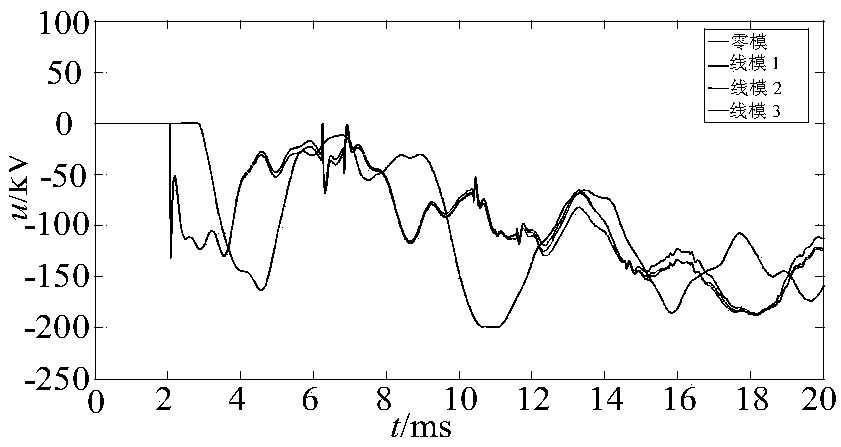
[0063] According to step 1, the fault component waveform of each pole-line voltage at the measuring terminal M on the rectification side is obtained, as shown in figure 2 As shown; according to step 2, using formula (2) to perform voltage decoupling transformation on the pole-line voltage mutation of the measuring terminal M, and obtain the voltage line mode component of the measuring terminal M, as shown in image 3 shown; according to step three, use formula (3) and formula (4) to calculate the voltage and current variation along the line; according to step four, ...

Embodiment 2

[0064] Embodiment 2: also adopt as figure 1 The shown ±500kV double-circuit DC transmission system on the same tower. The total length of the line is 1286km. Four-split conductors are used. 0.3H smoothing reactors are installed on both sides of the line. Each pole is connected with a single 12-pulse valve group. The rated transmission power is 6400MW and the rated current is 3200A. The sampling rate is set to 1MHZ. Assuming that the electrical quantity on the rectification side can be measured, if a metallic grounding fault occurs at a distance of 900km from the rectification side measurement terminal M900km away from the half-line length of the positive pole IP of the I return line.

[0065] According to step 1, the fault component waveform of each pole-line voltage at the measuring terminal M on the rectification side is obtained, as shown in Image 6 As shown; according to step 2, use formula (2) to perform voltage decoupling transformation on the sudden change of pole-li...


PUM


Abstract

The invention relates to a line-side energy mutation based single-end travelling wave fault location method for double DC circuits on the same tower and belongs to the technical field of power system relay protection. The method includes steps of obtaining voltage of a measuring end and solving a fault component and solving a line mode voltage component by adopting phase mode conversion when the double DC circuits on same tower meets a grounding fault; applying a Bergeron transfer equation and the measuring end line mode voltage component for calculating line-side voltage and current travelling wave variations; cubing a product of the line-side voltage traveling wave variation and the line-side current traveling wave variation and constructing a fault location function through integrating in an observation time window; realizing fault location through combining line-side mutation rules of the fault location function and the polarity of the wavelet transform modulus maxima of fault voltage traveling waves. According to the invention, fault location is performed for the double DC circuits on same tower and the principle is simple. Wave heads of the fault traveling waves do not need to marked and influence caused by fault instantaneity, fault transition resistance variation and the like is eliminated. The fault location result is accurate and reliable.

Description

technical field [0001] The invention relates to a method for single-end traveling wave distance measurement of a double-circuit DC line on the same tower based on energy mutation along the line, and belongs to the technical field of electric power system relay protection. Background technique [0002] The DC line is an important part of the double-circuit DC transmission system on the same tower. It has a high voltage level and a long transmission distance. During the process of transmitting large-capacity electric energy, the environment in the area passing by is harsh, and it is easy to cause failures. The precise positioning technology of the fault point of the DC line is helpful to quickly and accurately determine the fault location, reduce the blindness of line inspection, and accelerate the recovery of power transmission. The traveling wave principle is mostly used in DC line fault location. Most of the current traveling wave ranging methods are based on the time-doma...

Claims


Application Information

Patent Timeline
Patent Type & Authority Patents(China)
IPC IPC(8): G01R31/08
CPCG01R31/088
Inventor 田鑫萃束洪春
Owner KUNMING UNIV OF SCI & TECH
Why Eureka
Try Eureka