Multi-power-source inlet wire switch cabinet

A technology of incoming line switch and multi-power supply, which is applied in the field of switchgear, can solve the problems of switchgear losing function, achieve the effect of prolonging service life and ensuring safety

Active Publication Date: 2013-11-27
SUNRISE GRP CO LTD
View PDF7 Cites 1 Cited by
  • Summary
  • Abstract
  • Description
  • Claims
  • Application Information

AI Technical Summary

Problems solved by technology

[0002] A general switch cabinet can only be connected to one circuit. When the power supply line of this circuit loses power, the entire switch cabinet will lose its function.

Method used


Image

  • Multi-power-source inlet wire switch cabinet
  • Multi-power-source inlet wire switch cabinet
  • Multi-power-source inlet wire switch cabinet

Examples


Embodiment Construction

[0012] A preferred embodiment of a multi-power incoming switchgear of the present invention will be described in detail below in conjunction with the accompanying drawings:

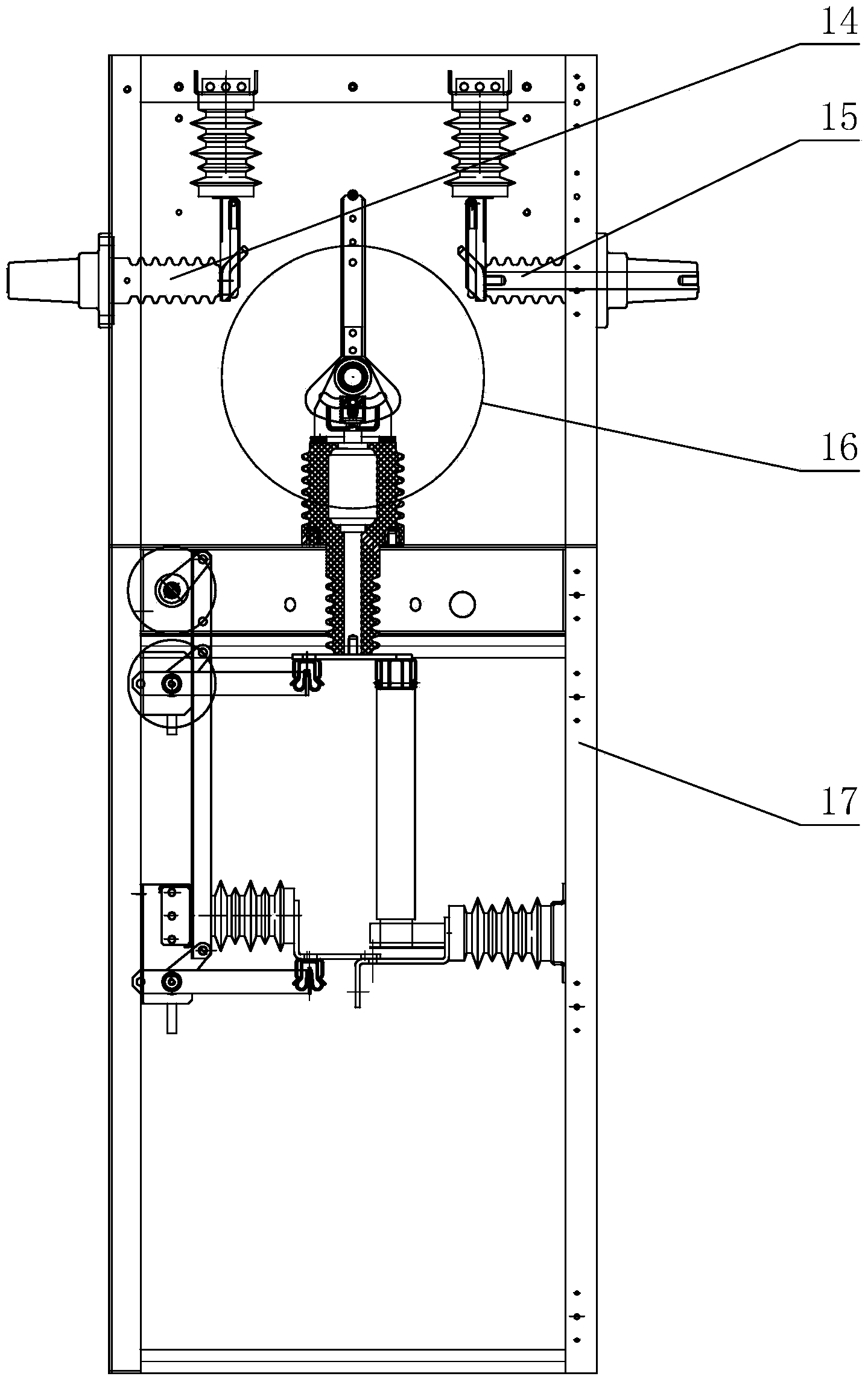
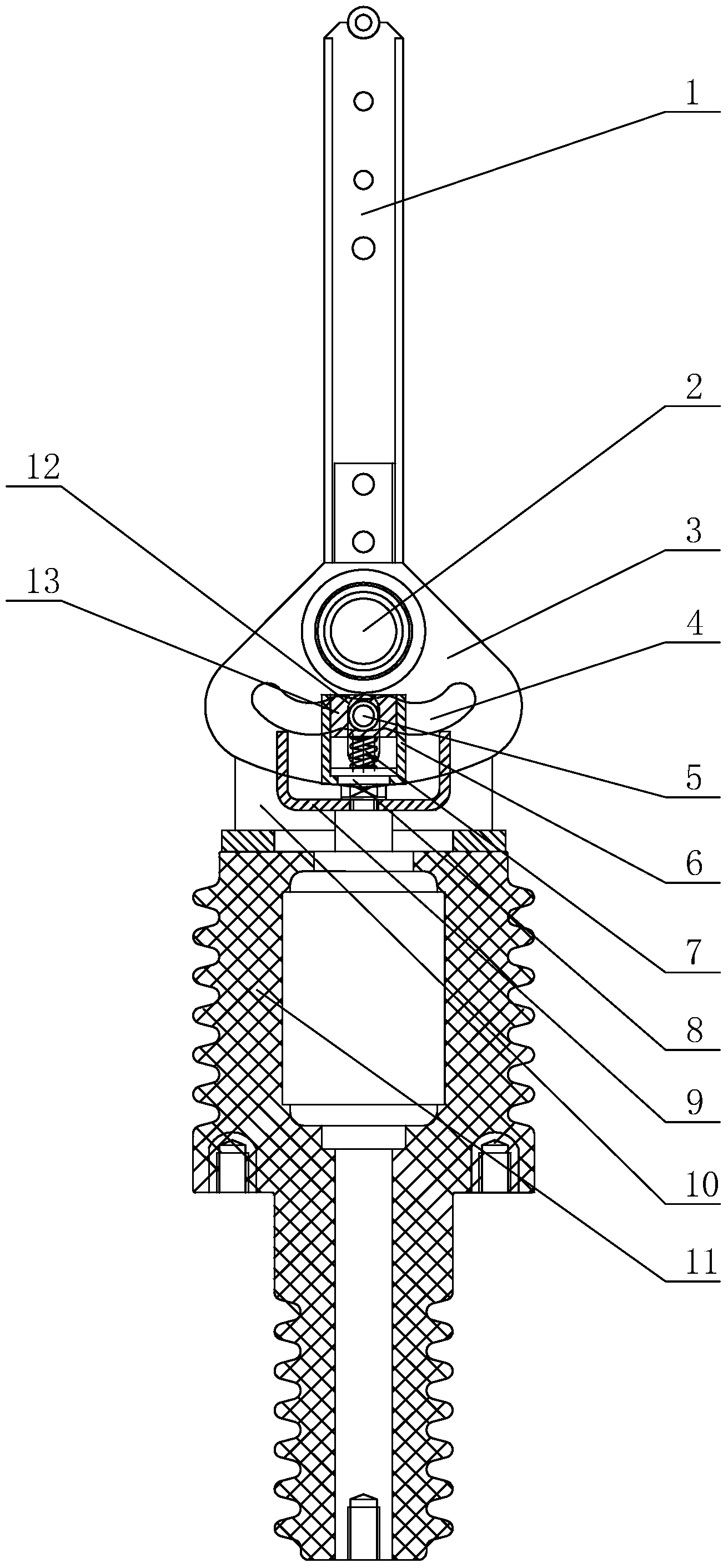
[0013] Such as figure 1 , figure 2 and image 3 As shown, the switchgear mainly includes a cabinet body 17, and the left and right power supply incoming lines 14 and 15 are respectively arranged on the left and right sides of the top of the cabinet body 17. Inside the cabinet body 17 is provided with a switch 16 that can selectively connect the left power supply incoming line 14 or the right power supply incoming line 15, and the switch 16 is located below the middle line of the left power supply incoming line 14 and the right power supply incoming line 15.

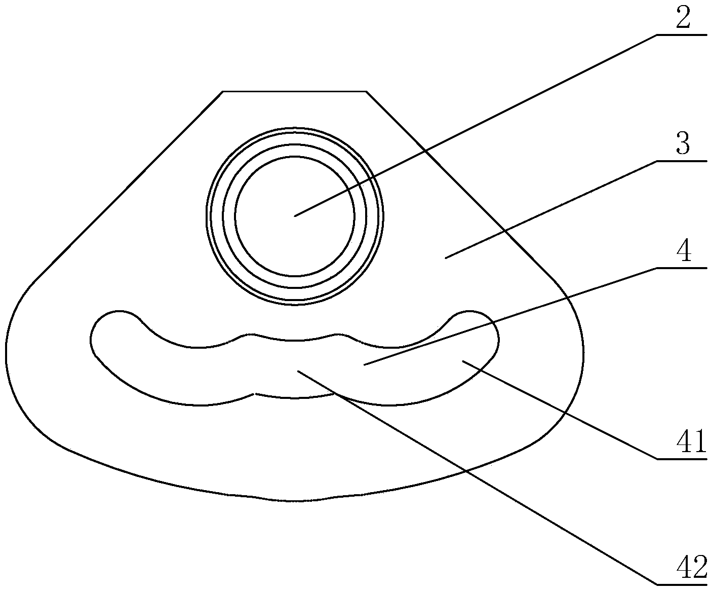
[0014] The switch 16 includes an isolation knife 1 and a vacuum interrupter solid-sealed pole 11 . The lower end of the isolation knife 1 is fixedly connected with the cam plate 3, the cam plate 3 is fixedly mounted on the insulating main shaft 2...


PUM


Abstract

The invention relates to a multi-power-source inlet wire switch cabinet. The multi-power-source inlet wire switch cabinet comprises a cabinet body, power source inlet wires are arranged on the cabinet body, and a switch selectively connected with any power source inlet wire is arranged near the power source inlet wires. The switch comprises an isolation cutter and a vacuum arc-extinguishing chamber fixed sealing pole pillar. The lower end of the isolation cutter is fixedly connected with a cam plate which is fixedly installed on an insulating main shaft. The insulating main shaft is rotatably arranged on a support. The lower end of the support is fixed on the top of the vacuum arc-extinguishing chamber fixed sealing pole pillar. A long hole is formed in the support. A cam groove is formed in the cam plate. A hinge pin penetrates through the long hole and the cam groove. The lower portion of the hinge pin is connected with an electric conduction soft connection part and a movable contactor together. The electric conduction soft connection part is electrically connected the isolation cutter. A static contactor is arranged on the lower portion of the vacuum arc-extinguishing chamber fixed sealing pole pillar. As the cam plate rotates, the hinge pin moves to a section away from the hinge pin to a section near the hinge pin of the cam groove, then the hinge pin drives a movable contactor to move downwards to be in contact with the static contactor for energizing, and the isolation cutter is connected with the power inlet wires when and only when the isolation cutter is powered on. The energizing process of the switch cabinet is continuous, and the inlet wires can be switched manually.

Description

technical field [0001] The invention relates to a switch cabinet, in particular to a switch cabinet with multiple power supply incoming lines. Background technique [0002] A general switch cabinet can only be connected to one circuit. When the power supply line of this circuit loses power, the entire switch cabinet will lose its function. Therefore, how to realize uninterrupted power supply of a switchgear, and how to switch on the power supply manually has become a technical problem. Contents of the invention [0003] The invention provides a multi-power incoming switchgear capable of selectively connecting multiple circuits. In order to realize the above-mentioned purpose of the invention, the present invention adopts the following technical means: [0004] A multi-power supply incoming switch cabinet, including a cabinet body; a power supply incoming line is arranged on the cabinet body; a switch capable of selectively connecting any power supply incoming line is arr...

Claims


Application Information

Patent Timeline
IPC IPC(8): H02B1/24H02B1/20H01H21/36
Inventor 樊建荣文化宾刘慧科胡伟成
Owner SUNRISE GRP CO LTD
Why Eureka
Try Eureka