Eureka AIR delivers breakthrough ideas for toughest innovation challenges, trusted by R&D personnel around the world.

Automatic creel lifting device of rotor spinning machine

A technology of rotor spinning machine and creel, which is applied in spinning machine, open-end spinning machine, continuous winding spinning machine, etc., can solve the problem of easy-wear yarn, low piecing success rate, waste yarn, etc. question

Active Publication Date: 2013-12-04
太仓满金机械有限公司
View PDF8 Cites 3 Cited by
  • Summary
  • Abstract
  • Description
  • Claims
  • Application Information

AI Technical Summary

Problems solved by technology

[0007] No matter what kind of yarn support rod is available, the yarn support rod is only a rod. When the yarn is automatically lifted, the yarn is rotating rapidly, and the lifting of the yarn support rod will stop the yarn instantly or the Sliding friction, it is easy to wear the yarn, resulting in waste yarn
In addition, when the joint is doffing, the yarn supporting rod needs to move backward for a certain distance, and the yarn needs to overcome the friction between the bobbin and the supporting yarn rod, which causes the doffing to be delayed, and the doffing is difficult when the large yarn is spliced, and the joint is successful. The efficiency is low, which affects the quality and efficiency of the joint, so the traditional structure of the yarn support rod has high requirements for the operation of the staff

Method used


Image

  • Automatic creel lifting device of rotor spinning machine
  • Automatic creel lifting device of rotor spinning machine
  • Automatic creel lifting device of rotor spinning machine

Examples


Embodiment Construction

[0031] The present invention will be further described in detail below in conjunction with the accompanying drawings and embodiments.

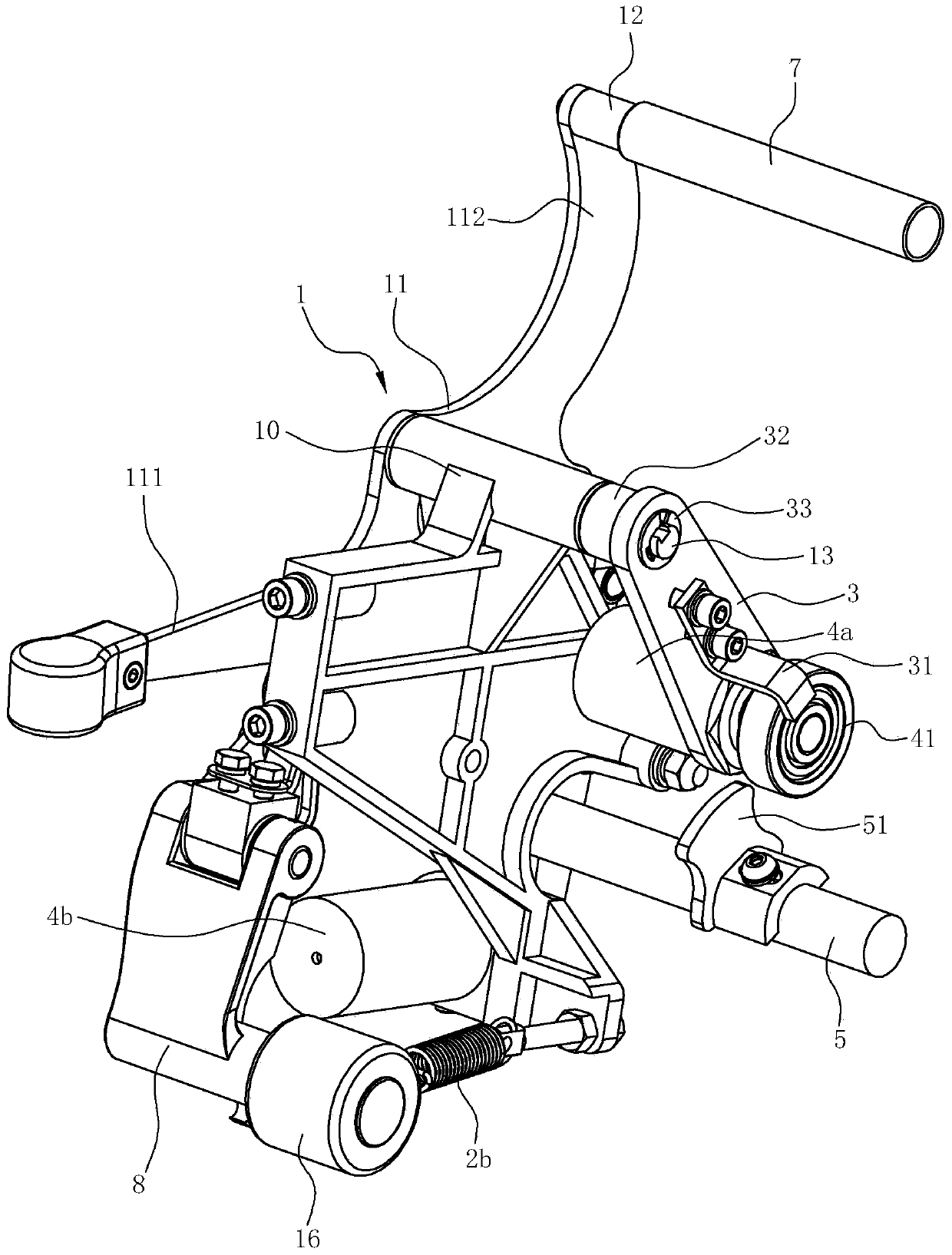
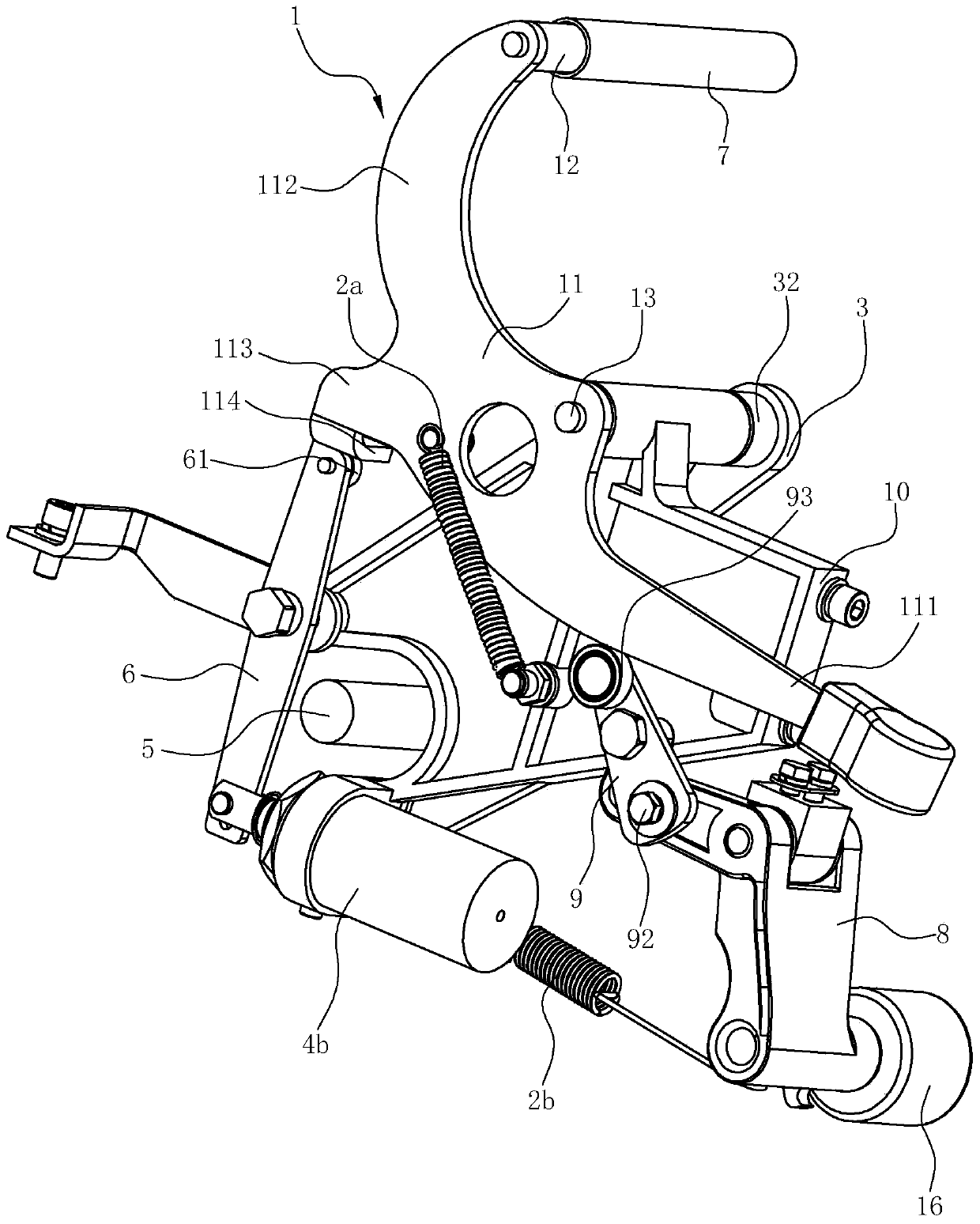
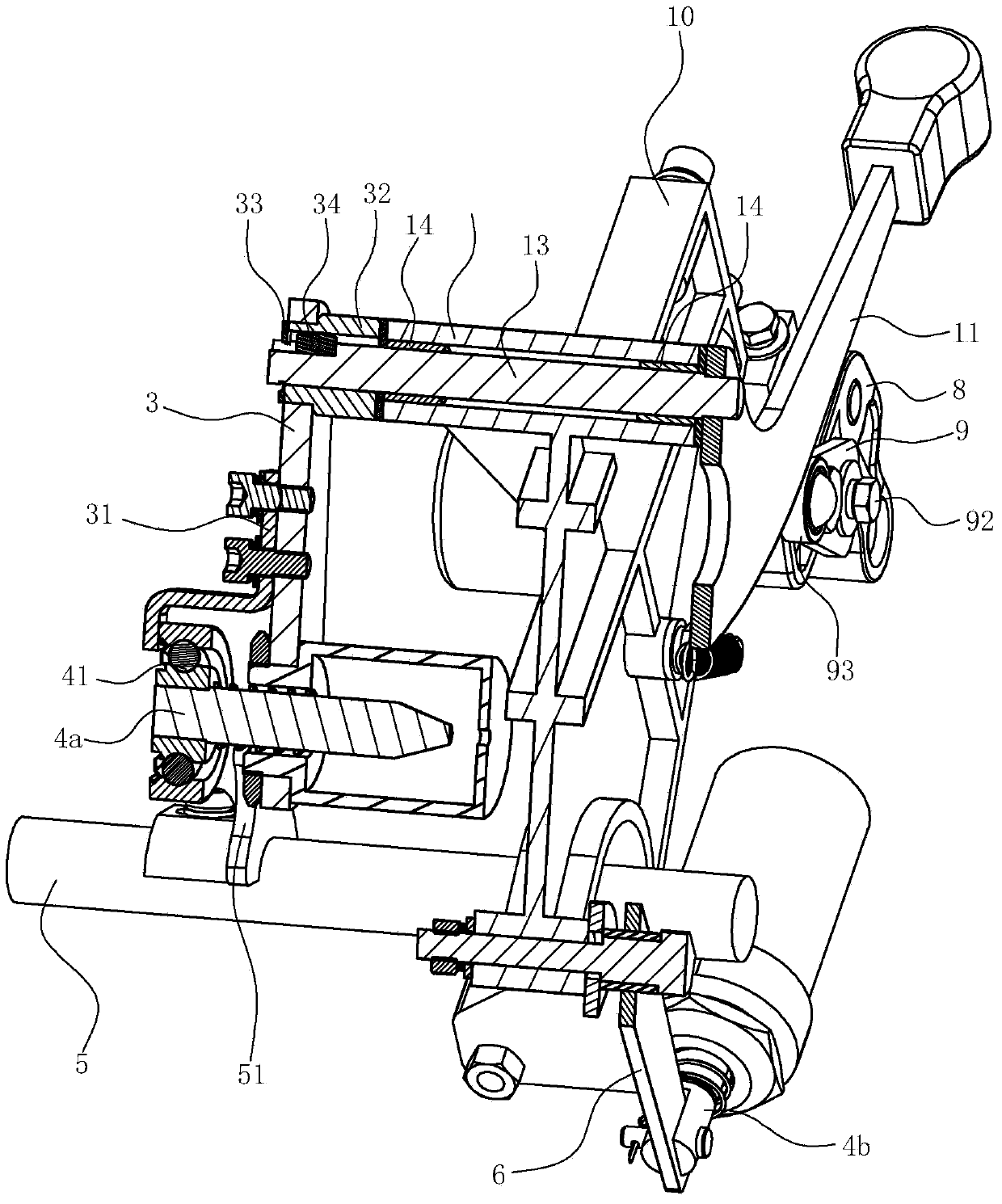
[0032] Such as Figure 1-10 Shown is a preferred embodiment of the present invention.

[0033] An automatic creel lifting device for a rotor spinning machine, comprising a mounting seat 10.

[0034] Yarn supporting rod 1, the yarn supporting rod 1 has a connecting arm 11, a yarn supporting rod 12 and a rotating shaft part 13, wherein the yarn supporting rod 12 is welded and fixed on the upper end of the vertical arm 112 in a horizontal direction, and the connecting arm 11 has a horizontal arm 111 and the vertical arm 112, the vertical arm 112 is located at the front part of the horizontal arm 111, the vertical arm 112 is arc-shaped, the upward flip of the connecting arm 11 can allow the yarn supporting rod part 12 to lift the creel 17, and the shaft part 13 is horizontal Fixed on the middle part of the connecting arm 11, the rotating shaft p...


PUM


Abstract

The invention relates to an automatic creel lifting device of a rotor spinning machine. The automatic creel lifting device of the rotor spinning machine is characterized in that the device comprises an installation base, a yarn carrying rod piece, a first spring, a lifting arm, a first electromagnet, a lifting arm cam and a supporting arm, the yarn carrying rod piece is provided with a connecting arm, a yarn carrying rod part and a rotary shaft part, the rotary shaft part is installed on the installation base in a rotary mode, the first spring is connected between the installation base and the connecting arm, the lifting arm is fixed on the end portion of the rotary shaft part, the first electromagnet is fixed on the lower portion of the lifting arm, a first bearing is installed on the end portion of an iron core of the first electromagnet, the lifting arm cam is fixed on the rotary shaft, and the middle of the supporting arm is connected to the installation base in a rotary mode. According to the automatic creel lifting device of the rotor spinning machine, when a yarn breaking signal is transmitted to the first electromagnet, the first bearing is made in contact with the lifting arm cam rotating along with the rotary shaft, the movement of the lifting arm cam enables the lifting arm to deviate, then the whole yarn carrying rod piece is driven to deviate upwards to lift a creel, and then the automatic yarn lifting function of the creel is achieved.

Description

technical field [0001] The invention belongs to the technical field of spinning machinery and equipment, and in particular relates to an automatic creel lifting device of a rotor spinning machine. Background technique [0002] The rotor spinning machine is a new type of spinning equipment with rapid development. The yarn drawing speed and spinning count are getting higher and higher. The manual yarn lifting currently used is labor-intensive. The starting of the yarn will make the yarn rub against the winding roller all the time, which is easy to wear the yarn, and the efficiency is poor. [0003] At present, the semi-automatic piecing device of the rotor spinning machine on the market uses the force generated in the closed state of the electromagnet to drive the top roller and the yarn delivery shaft to prepare for the piecing through the locking linkage mechanism. For example, a Chinese utility model patent "A New Semi-automatic Jointing Mechanism for a Rotor Spinning Mach...

Claims


Application Information

Patent Timeline
Patent Type & Authority Applications(China)
IPC IPC(8): D01H4/50
Inventor 石焕强朱槐林王敏程建辉梁汉超王云
Owner 太仓满金机械有限公司
Why Eureka
Eureka Blog
Learn More