Offset error compensation systems and methods in sensors

An offset error, sensor technology, applied in the field of sensors

Inactive Publication Date: 2013-12-04
INFINEON TECH AG
View PDF4 Cites 14 Cited by
  • Summary
  • Abstract
  • Description
  • Claims
  • Application Information

AI Technical Summary

Problems solved by technology

However, this method still produces a sma...

Method used


Image

  • Offset error compensation systems and methods in sensors
  • Offset error compensation systems and methods in sensors
  • Offset error compensation systems and methods in sensors

Examples


Embodiment Construction

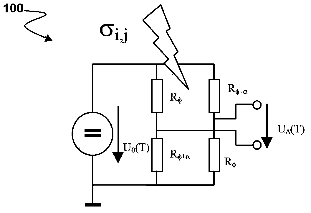
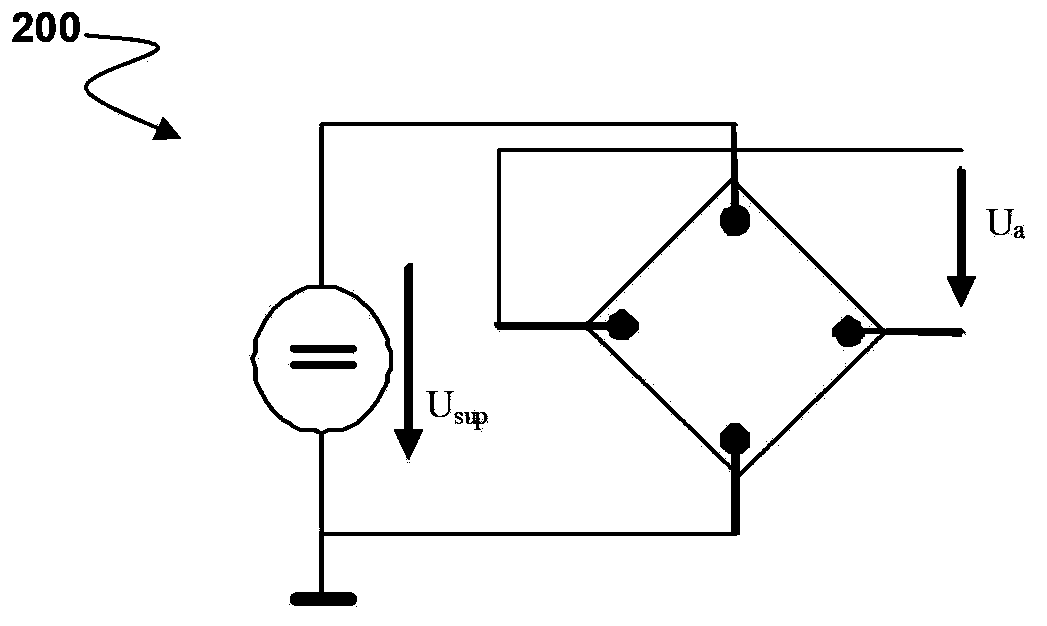
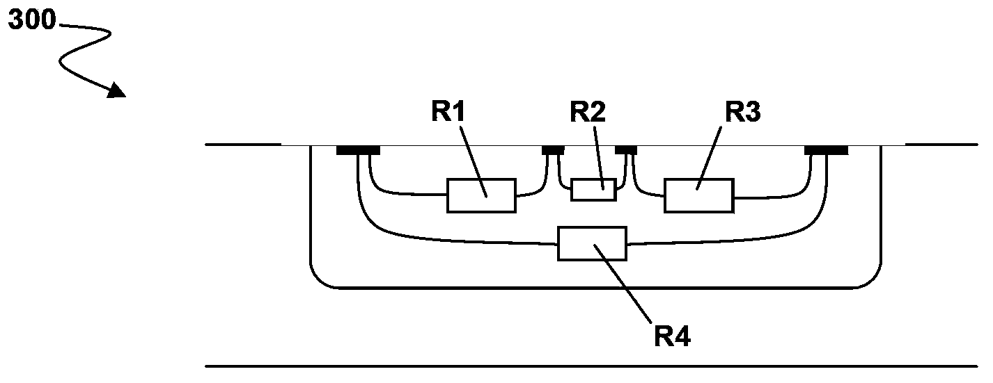
[0015] Embodiments relate to reducing offset errors in sensor systems. In an embodiment, the sensitivity and offset of the sensor depend differently on certain parameters (eg, voltage) such that operating the sensor at two different parameter values ​​cancels the offset error. implementation is suitable for strain sensors ( figure 1 ), Hall plate ( figure 2 ), vertical Hall device ( image 3 ), magnetoresistive sensors and others.

[0016] Sensitivity S and offset Off of the sensor depend differently on certain parameters, eg supply voltage. In an embodiment, operation of the sensor at a first supply voltage Usup1 and a second supply voltage Usup2 provides two different output signals Ua1 and Ua2 which depend respectively on two unknown quantities: measured by the sensor The physical quantity Q and offset Off. That is to say:

[0017] Ua1=S1Q+Off1

[0018] Ua2=S2Q+Off2

[0019] It can be found that certain linear combinations of signals will remove the offset:

[002...


PUM


Abstract

The embodiments of the invention relates to offset error compensation systems and methods in sensors. Embodiments relate to reducing offset error in sensor systems. In embodiments, the sensitivity and offset of a sensor depend differently on some parameter, e.g. voltage, such that operating the sensor at two different values of the parameter can cancel the offset error. Embodiments can have applicability to stress sensors, Hall plates, vertical Hall devices, magnetoresistive sensors and others.

Description

technical field [0001] The present invention relates generally to sensors, and more particularly to compensation for offset errors in sensors. Background technique [0002] Sensors are often used as sensor bridges, for example with four identical sensor elements coupled in a Wheatstone bridge configuration. The bridge circuit is supplied with voltage or current and provides different output voltages. Examples of this include strain sensors, magnetoresistive sensors, Hall plates, and vertical Hall devices, among others. [0003] However, a common problem with sensor bridges is offset error. Offset is the output signal when there is no physical quantity that the sensor should detect. For example. For a Hall plate, the offset is the output signal at zero applied magnetic field, and for a stress sensor, the offset is the output signal at zero mechanical stress. Typically, the source of offset error is a small mismatch between the sensor elements of the bridge. In other wor...

Claims


Application Information

Patent Timeline
IPC IPC(8): G01D3/032
CPCG01D5/14G01R33/072G01R33/07G01D3/032G01R33/091G01R17/00G01R33/09G01D3/02G01D3/036G01D5/145G01L1/12G01R35/00
Inventor 乌多·奥塞尔勒基纳马里奥·莫茨
Owner INFINEON TECH AG
Why Eureka
Try Eureka