Environmental control power distribution cabinet

A power distribution cabinet and environmental control technology, which is applied in the direction of substation/power distribution device housing, etc., can solve the problems of increased cost, low safety, and high cost, and achieve the effects of reducing maintenance cost, improving safety, and increasing strength

Inactive Publication Date: 2013-12-04
SHANGHAI ZHEZHONG ELECTRIC
View PDF9 Cites 1 Cited by
  • Summary
  • Abstract
  • Description
  • Claims
  • Application Information

AI Technical Summary

Problems solved by technology

[0003] The frame of the environmental control electric control cabinet is usually made of profiles. Because the traditional frame profiles have the function of dustproof and waterproof, the environmental control electric control cabinet is easy to accumulate dust and water, which will affect the work of the electric control cabinet and even damage the electric control cabinet. cabinet, increasing the cost
[0004] The front of the door panel of the traditional environmental control electric control cabinet is usually equipped with various switches and indicator lights. The wiring of the switches and indicator lights is directly connected to the cabinet from the back of the door panel. Very inconvenient when cleaning
[0005] At the same time, due to the need for strength, the door panels of traditional environmental control electric control cabinets usually make the door panels more than 2.5mm, which is costly
[0006] In addition, the door of the environmental control power distribution cabinet is usually outward-opening. Since the hinges of the traditional environmental control power distribution cabinet doors are often exposed outside the cabinet, they are easy to be disassembled and damaged, and the safety is low.

Method used


Image

  • Environmental control power distribution cabinet
  • Environmental control power distribution cabinet
  • Environmental control power distribution cabinet

Examples


Embodiment Construction

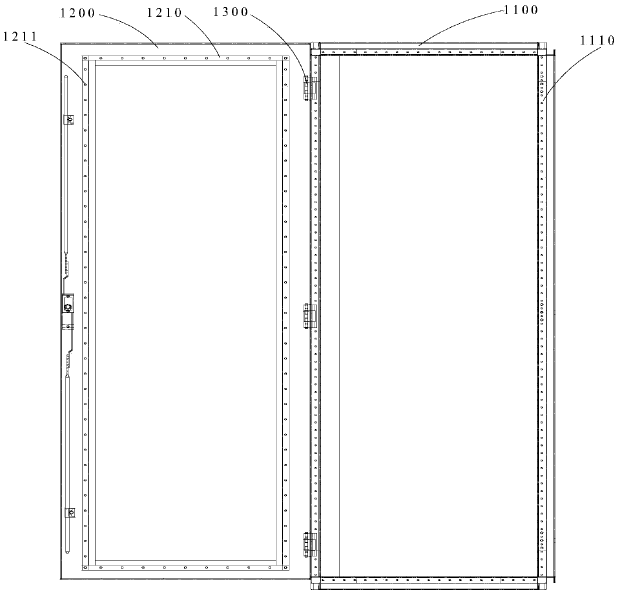
[0026] Such as figure 1 As shown, a door of an environmental control power distribution cabinet includes a door frame 1100 , a door panel 1200 and a plurality of hinges 1300 .

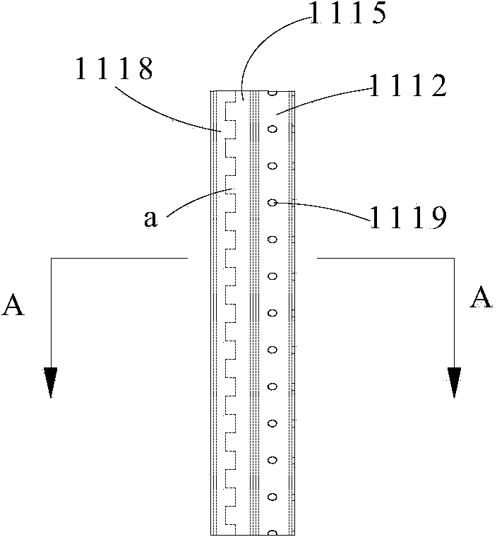
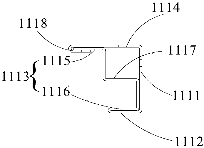
[0027] Such as Figure 1-3 As shown, the door frame 1100 is composed of a plurality of frame profiles 1110 to form a rectangular parallelepiped frame structure, and the frame profiles 1110 include an inner side panel 1111 , a front side panel 1112 , a reinforcement panel 1113 and a rear side panel 1114 .

[0028] The front and rear edges of the inner side board 1111 are vertically connected with the front side board 1112 and the rear side board 1114 outward respectively.

[0029] The front side plate 1112 is used for water discharge and dustproof of the power distribution cabinet, and it is shorter than the rear side plate 1114 .

[0030] The reinforcing plate 1113 includes a plate body 1115 and an L-shaped plate body 1116 , and the plate body 1115 is integrally connected with the L-shaped plate body...


PUM


Abstract

An environmental control power distribution cabinet comprises a door frame, a door plate and a plurality of hinges. The door frame is of a cuboid frame structure composed of a plurality of frame sectional materials. The frame sectional materials comprise an inner lateral plate, a front lateral plate, a reinforcing plate and a rear lateral plate. A wire arranging frame is arranged on the back face of the door plate, and a plurality of wire binding holes are evenly formed in the wire arranging frame. The hinges comprise hinge bases, hinge columns and bolts. The hinge bases of the hinges are evenly arranged on the door frame, hinge arms which are arranged at an interval and extend towards the outer side of the power distribution cabinet are arranged on each hinge base, concentric first bolt holes are formed in every two hinge columns respectively, the hinge columns of the hinges are evenly arranged on the back face of the door plate, each hinge column is respectively located between the two corresponding hinge arms, two bolt holes are evenly formed in each hinge column, and the bolts of the hinges are inserted in the first bolt holes and the second hole holes respectively. The environmental control power distribution cabinet is high in strength, god in waterproof and dustproof performance, convenient to maintain, low in cost and high in cabinet body safety.

Description

technical field [0001] The invention relates to a power distribution cabinet, in particular to an environment-controlled power distribution cabinet. Background technique [0002] The environmental control electric control cabinet is used to provide power for ventilation and air conditioning equipment in subway stations and sections. [0003] The frame of the environmental control electric control cabinet is usually made of profiles. Because the traditional frame profiles have the function of dustproof and waterproof, the environmental control electric control cabinet is easy to accumulate dust and water, which will affect the work of the electric control cabinet and even damage the electric control cabinet. cabinet, which increases the cost. [0004] The front of the door panel of the traditional environmental control electric control cabinet is usually equipped with various switches and indicator lights. The wiring of the switches and indicator lights is directly connected...

Claims


Application Information

Patent Timeline
Patent Type & Authority Applications(China)
IPC IPC(8): H02B1/26
Inventor 汪东王坚祝延辉
Owner SHANGHAI ZHEZHONG ELECTRIC
Why Eureka
Try Eureka