
A Method of Filtering Glitch Based on Synchronous Circuit
A synchronous circuit and filtering technology, applied in pulse shaping and other directions, can solve the problems of difficult to achieve logic synthesis
- Summary
- Abstract
- Description
- Claims
- Application Information
AI Technical Summary
Problems solved by technology
Method used
Image

Examples
Embodiment Construction
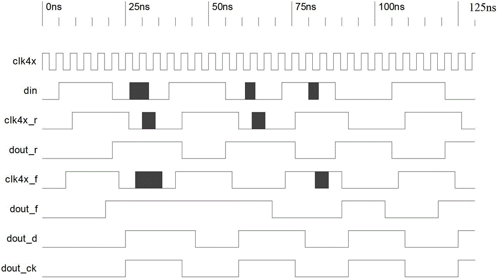
[0021] The invention provides a method for filtering burrs based on a synchronous circuit, the method comprising the following steps:
[0022] 1) Use the rising edge and falling edge of the low sampling clock to sample the input signal respectively, and obtain the rising edge sampling signal and the falling edge sampling signal;
[0023] 2) Reshape the rising edge sampling signal and the falling edge sampling signal to obtain the shaped rising edge sampling signal and the shaped falling edge sampling signal;
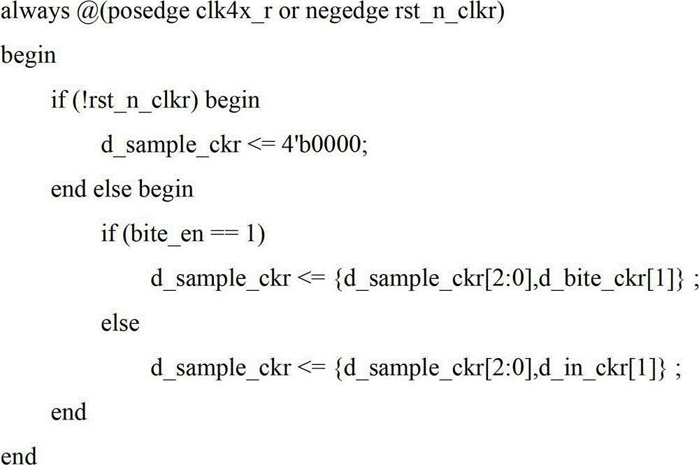
[0024] 2.1) Put the rising edge sampling signal acquired by the rising edge and the falling edge sampling signal acquired by the falling edge into the 4-bit shift register respectively;
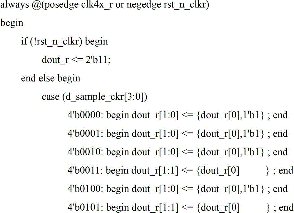
[0025] 2.2) According to the value in the 4-bit shift register, judge the rising edge sampling signal and the falling edge sampling signal respectively, and output the shaped rising edge sampling signal and the shaped falling edge sampling signal:
[0026] If at least 3 of the sampling...
PUM
 Abstract
Description
Claims
Application Information