Electromagnetic shape righting device and shape righting method
An orthopedic and electromagnetic technology, used in forming tools, manufacturing tools, metal processing equipment, etc., can solve the problems of increasing the distance between the local area of the plate and the coil, increasing the manufacturing cost, and reducing the strength of the magnetic field. Orthopedic requirements, reducing design and manufacturing costs, and enhancing the effect of forming magnetic field strength
- Summary
- Abstract
- Description
- Claims
- Application Information
AI Technical Summary
Problems solved by technology
Method used
Image
Examples
Embodiment 1
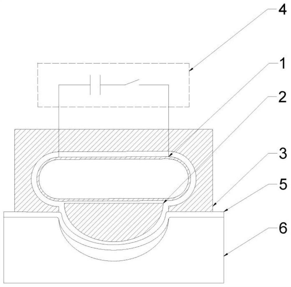
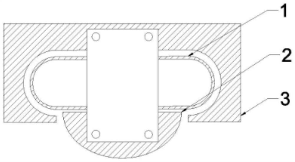
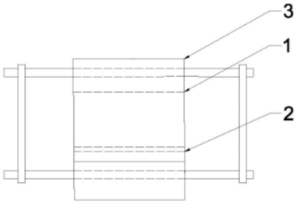
[0069] Such as Figure 4 As shown, an embodiment of the present invention provides an electromagnetic orthopedic device and an orthopedic method based on the device, which are used for orthoping a workpiece whose forming accuracy is insufficient due to the springback of the plate material. The electromagnetic orthopedic device includes: a uniform pressure drive coil 1 , a magnetic field shaper 2 , a conductive channel 3 , a power supply 4 , a workpiece to be orthopedic 5 and a mold 6 . Among them, the uniform pressure driving coil 1 is a uniform pressure coil wound with a single layer of copper wire, the cross-sectional size of the wire is 2mm×4mm, and a total of 18 turns; the lower surface contour of the magnetic field shaper 2 is the same as the inner contour of the mold, and the material is copper. The magnetic field shaper 2 is mechanically connected to the conductive channel 3 to constrain its position; the inner contour of the conductive channel 3 is the same as the oute...
Embodiment 2
[0077] Such as Figure 5 As shown, one embodiment of the present invention provides an electromagnetic orthopedic device and an orthopedic method based on the device, which are used for multiple progressive shaping of a long straight plate. The electromagnetic orthopedic device includes: a uniform pressure driving coil 1 , a magnetic field shaper 2 , a conductive channel 3 , a power source 4 , a workpiece 5 and a mold 6 . Among them, the uniform pressure driving coil 1 is a uniform pressure coil wound with a single layer of copper wire, the cross-sectional size of the wire is 2mm×4mm, and a total of 18 turns; the lower surface contour of the magnetic field shaper 2 is the same as the inner contour of the mold, and the material is copper. The magnetic field shaper 2 is mechanically connected to the conductive channel 3 to constrain its position; the inner contour of the conductive channel 3 is the same as the outer surface contour of the uniform pressure drive coil 1, and the m...
Embodiment 3
[0087] Such as Figure 6As shown, an embodiment of the present invention provides an electromagnetic orthopedic device and an orthopedic method based on the device, which are used to shape a preformed workpiece with local complex features. The electromagnetic orthopedic device includes: a uniform pressure driving coil 1 , a magnetic field shaper 2 , a conductive channel 3 , a power source 4 , a workpiece 5 and a mold 6 . Among them, the uniform pressure driving coil 1 is a uniform pressure coil wound with a single layer of copper wire, and the cross-sectional size of the wire is 2mm×4mm, with 18 turns in total; A mechanical connection is made between the shaper 2 and the conductive channel 3 to constrain its position; the inner contour of the conductive channel 3 is the same as the outer surface contour of the uniform pressure drive coil 1, and the material is copper; the power supply 4 is a capacitive energy storage type power supply system, provided Coil waveform such as ...
PUM
 Abstract
Description
Claims
Application Information
 - R&D
- Intellectual Property
- Life Sciences
- Materials
- Tech Scout
- Unparalleled Data Quality
- Higher Quality Content
- 60% Fewer Hallucinations
Browse by: Latest US Patents, China's latest patents, Technical Efficacy Thesaurus, Application Domain, Technology Topic, Popular Technical Reports.
© 2025 PatSnap. All rights reserved.Legal|Privacy policy|Modern Slavery Act Transparency Statement|Sitemap|About US| Contact US: help@patsnap.com


