Lifting point of plate-type traction shell flange

A cylinder flange and plate type technology, applied in the direction of load hanging components, transportation and packaging, etc., can solve the problems of deformation, large local stress of equipment, etc., and achieve the effect of reducing bending, good stress state, and smooth movement

Inactive Publication Date: 2013-12-11
CHINA NAT OFFSHORE OIL CORP +2
View PDF5 Cites 4 Cited by
  • Summary
  • Abstract
  • Description
  • Claims
  • Application Information

AI Technical Summary

Problems solved by technology

If the operation is not done properly, the local stress of the equipment will be too large and cause deformation

Method used


Image

  • Lifting point of plate-type traction shell flange
  • Lifting point of plate-type traction shell flange
  • Lifting point of plate-type traction shell flange

Examples


Embodiment Construction

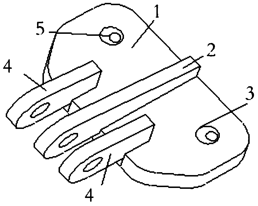
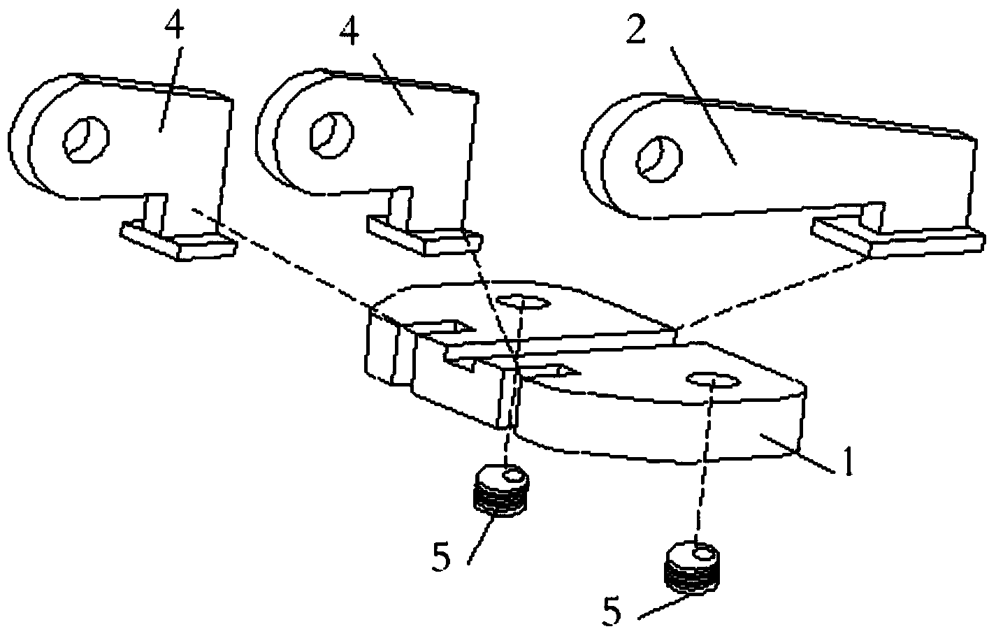
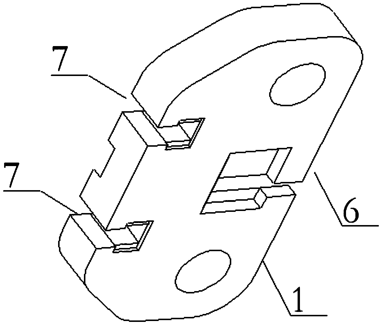
[0024] Such as figure 1 — image 3 As shown, the present invention includes: a hanging point connecting plate 1 arranged at the bottom, a traction eye plate 2 vertically fixed on the lifting point connecting plate 1, wherein the hanging point connecting plate 1 is provided with several threaded holes 3, and the threaded holes 3 is installed with a threaded bushing 5 by threaded connection; the middle part of the hanging point connecting plate 4 is also provided with a stepped groove 6 from one end of the hanging point connecting plate 4 to the other end, and the traction eye plate 2 is clamped on the hanging point connecting plate 4. In the stepped groove 6 of the plate 4; one side of the hanging point connecting plate 4 is provided with several stepped grooves 7, and the stepped grooves 7 are symmetrically arranged on both sides of the stepped groove 6; Strengthen the eye panel4.

[0025] The above-mentioned traction eye plate 2 is an L-shaped structure, one end of the L-sh...


PUM


Abstract

The invention relates to a lifting point of a plate-type traction shell flange, which comprises a lifting point connecting plate arranged on the bottom, and a traction eye plate perpendicularly fixed to the lifting point connecting plate, wherein the lifting point connecting plate is provided with a plurality of threaded holes; a thread bushing is respectively installed in each threaded hole; the middle part of the lifting point connecting plate is provided with a staircase groove from one end to the other end of the lifting point connecting plate; and the traction eye plate is clamped in the staircase groove in the lifting point connecting plate. When horizontally lifting the shell or overturning the shell, only simple adjustment is needed to implement connection and fixation between two flange end surfaces, and the motions of lifting and overturning of the shell can be smooth; and meanwhile, the shell is always in the favorable stressed state, thereby lowering the risks of bending, compression deformation and tearing of the lifting point.

Description

technical field [0001] The invention relates to a lifting point, in particular to a lifting point of a flange of a plate-type traction cylinder. It belongs to the field of marine engineering, wind power equipment installation and chemical construction. Background technique [0002] During the construction of marine engineering, the installation of wind power equipment and the construction of large-scale chemical plants on land, it is necessary to install many cylindrical facilities with flanged end faces. When installing, adjusting the cylinder from a horizontal state to a vertical state is an essential step in the installation process. Since there is no lifting point on the cylinder, when it is turned over, it can only be directly tied to the flange of the cylinder with a steel wire rope. If the operation is not done properly, the local stress of the equipment will be too large and cause deformation. Contents of the invention [0003] The main purpose of the present in...

Claims


Application Information

Patent Timeline
Patent Type & Authority Applications(China)
IPC IPC(8): B66C1/12
Inventor 李淑民鞠学国
Owner CHINA NAT OFFSHORE OIL CORP
Why Eureka
Try Eureka