Energy-saving bladeless fan

A bladeless fan and impeller technology, applied in the direction of liquid variable displacement machinery, pump devices, machines/engines, etc., can solve problems such as flapping, sound of fan blades, troubles, etc., and achieve soft airflow and easy cleaning

Inactive Publication Date: 2013-12-11
席新峰
View PDF0 Cites 0 Cited by
  • Summary
  • Abstract
  • Description
  • Claims
  • Application Information

AI Technical Summary

Problems solved by technology

[0003] The present invention aims at the problems existing in the above-mentioned products, and provides an energy-saving bladeless fan, which solves the problem that the rotating blades of the above-mentioned products require a large amount of electricity, and the fan needs to be disassembled for cleaning, and the blades must be cleaned and reassembled. It is more troublesome, and there will be sound when the fan blades rotate, which will affect people's rest at night, and there will be a feeling of flapping, making people very uncomfortable and other problems

Method used


Image

  • Energy-saving bladeless fan

Examples


Embodiment Construction

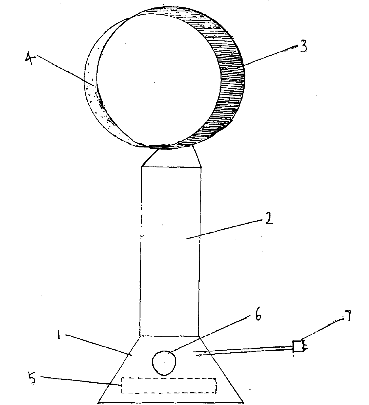
[0007] An energy-saving bladeless fan, comprising a base 1, a bracket 2, a circular edge 3, an impeller 4, a suction hole 5, a switch 6, and a power supply 7, the base 1 is located at the bottom, the base 1 is provided with a suction hole 5, and the bracket 2 is above the circular edge 3, the impeller 4 is hidden in the inside of the circular edge 3, and the switch 6 and the power supply 7 are all located on the base, which is convenient for use. The working steps are: suction, the air suction hole sucks air from the bottom of the electric fan; acceleration, the air enters the circular edge, and then creates a powerful jet airflow through the ring aperture; guide, the airflow passes through a 16-degree angled spiral wing shape The air guide slope, blowing out the air; induction, the air behind the fan is introduced into the airflow, this process is called induction; entrainment, the air around the machine is also drawn into the airflow, this process is called entrainment; reinf...


PUM


Abstract

The invention discloses an energy-saving bladeless fan. The energy-saving bladeless fan comprises a base, a support, a circular edge, an impeller, an air-inhaling hole, a switch and a power supply, wherein the base is located on the lowest portion and supports the whole fan; the air-inhaling hole is formed in the lower portion of the base; the circular edge is arranged above the support and facilitates airflow collection, and airflow is sprayed outwards along a circular trace; the impeller is hidden inside the circular edge; the switch and the power supply are arranged on the base and facilitate use. The energy-saving bladeless fan works according to the first step of inhaling, namely, air is inhaled from the bottom layer of the fan through the air-inhaling hole, the second step of accelerating, namely, the air enters the circular edge and makes strong injection airflow through the annular aperture, the third step of guiding, namely, the airflow passes through a 16-degree spiral wing-shaped air guide slope, and air is blown outwards, the fourth step of inducing, namely, air behind the fan is introduced to the airflow, the fifth step of clamping and involving, namely, air around the fan is involved in the airflow and the sixth step of reinforcing, namely, the airflow is instantly reinforced through air inducing, clamping and involving.

Description

technical field [0001] The invention relates to a fan, in particular to an energy-saving bladeless fan. Background technique [0002] The fan is a must-have item for people’s life in hot summer, but the rotating fan blades require a lot of electricity, and to clean it, you need to disassemble the fan, clean the fan blades and reinstall them, which is troublesome, and there will be noise when the fan blades rotate , It will affect people's rest at night, and there is a feeling of beating, which makes people very uncomfortable. Contents of the invention [0003] The present invention aims at the problems existing in the above-mentioned products, and provides an energy-saving bladeless fan, which solves the problem that the rotating blades of the above-mentioned products require a large amount of electricity, and the fan needs to be disassembled for cleaning, and the blades must be cleaned and reassembled. It is more troublesome, and there will be sound when the fan blades r...

Claims


Application Information

Patent Timeline
Patent Type & Authority Applications(China)
IPC IPC(8): F04B41/06
Inventor 席新峰
Owner 席新峰
Why Eureka
Try Eureka