Engine balance shaft

A balance shaft and engine technology, applied in the direction of inertial force compensation, etc., can solve problems such as the inability to change the balance rate, poor engine operation, and failure of the balance shaft, and achieve a strong versatility

Active Publication Date: 2013-12-11
GREAT WALL MOTOR CO LTD
View PDF5 Cites 13 Cited by
  • Summary
  • Abstract
  • Description
  • Claims
  • Application Information

AI Technical Summary

Problems solved by technology

Since the vibration of the engine is calculated, different engine parameters will require different balance forces to balance the engine, and the existing balance shafts are all fixed balance shafts for calculating the unbalance, and the balance rate cannot be changed, resulting in a balance The universality of the shaft is poor. In addition, the unbalance amount required by the engine at different speeds is also different. Although the difference is small, the balance shaft may cause resonance of the engine when the engine is started, resulting in failure of the balance shaft and causing the engine to work worse

Method used


Image

  • Engine balance shaft
  • Engine balance shaft

Examples


Embodiment Construction

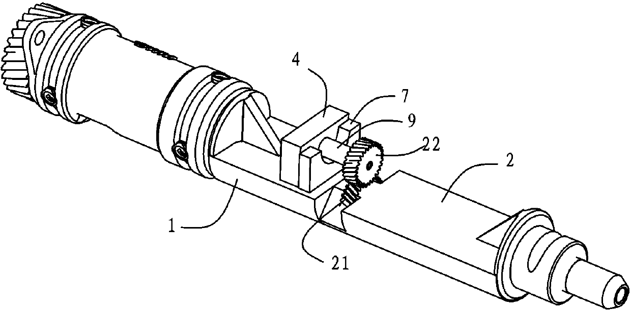
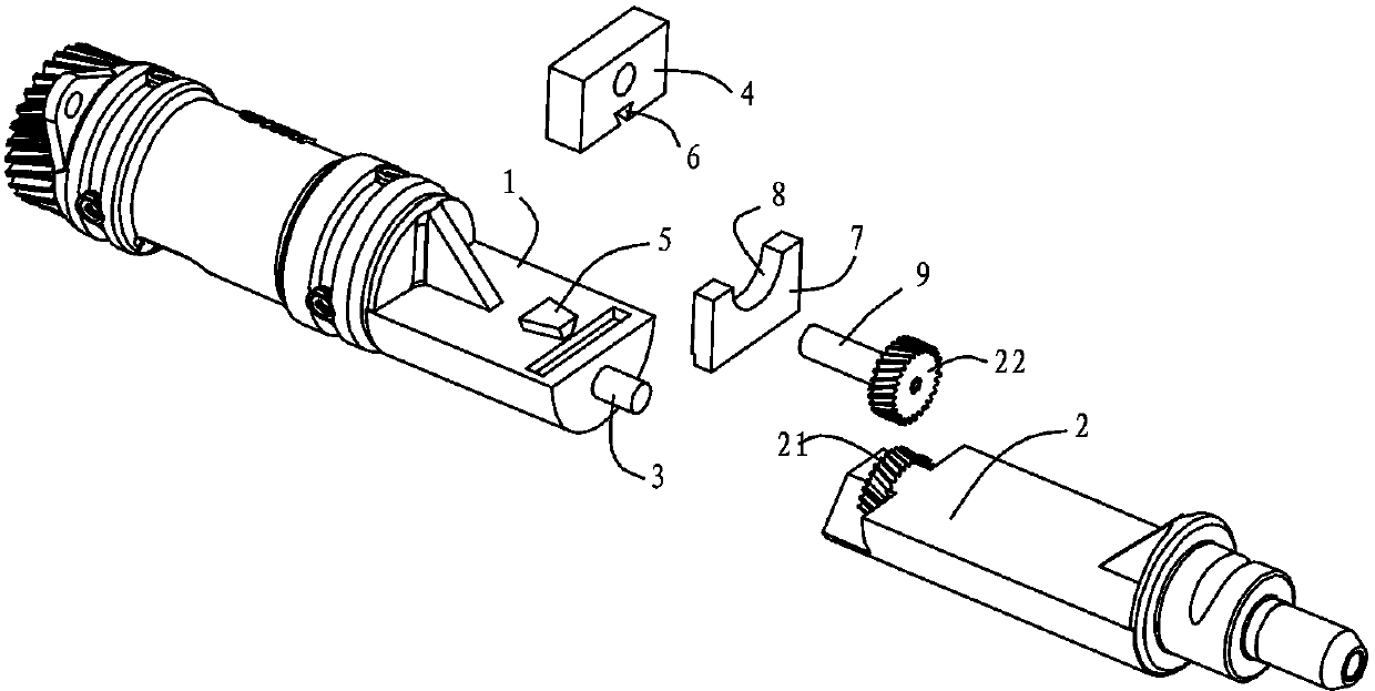
[0016] Depend on figure 1 combine figure 2 As shown, the present embodiment relates to a balance shaft of an engine, which has a first balance weight 1 and a second balance weight 2 whose mass is greater than that of the first balance weight 1, and the main body cross-sectional shapes of the first balance weight 1 and the second balance weight 2 are semicircular, both figure 1 The upper surface of the shown state is a plane. On the end face of the first balance weight 1 opposite to the second balance weight 2, a rotating shaft 3 is fixed. Correspondingly, the second balance weight 2 is provided with a diameter slightly larger than the diameter of the rotating shaft 3, not shown in the figure. The hole shown, in this way, when the rotating shaft 3 is inserted into the hole, the connection between the first balance weight 1 and the second balance weight 2 is realized, and the two can rotate relative to the rotating shaft 3 as the axis, and the connected second balance weight ...


PUM


Abstract

The invention relates to a balance shaft structure, in particular to an engine balance shaft. The engine balance shaft is provided with a first balance block and a second balance block, wherein the first balance block is connected with the second balance block through a rotary shaft; the engine balance shaft further comprises a drive device which drives the second balance block to rotate relative to the first balance block, and the second balance block is rotated by taking the rotary shaft as a shaft. The drive device drives the second balance block to enable the relative angle between the first balance block and the second balance block to be adjusted, the adjustment to the whole unbalance amount of the balance shaft is achieved, therefore, the engine balance shaft changes the equilibrium rate of an engine during running, meets the requirement of different revolving speeds of the engine, can adapt to unbalance amount needed by different engines, and improves universality.

Description

technical field [0001] The invention relates to a balance shaft structure, in particular to an engine balance shaft. Background technique [0002] The engine balance shaft has been widely recognized and applied because it can balance the second-order reciprocating inertial force and overturning moment of the engine, reduce the vibration and noise of the engine, improve the durability and reliability of parts, and improve the driving comfort of passengers. Since the vibration of the engine is calculated, different engine parameters will require different balance forces to balance the engine, and the existing balance shafts are all fixed balance shafts for calculating the unbalance, and the balance rate cannot be changed, resulting in a balance The universality of the shaft is poor. In addition, the unbalance amount required by the engine at different speeds is also different. Although the difference is small, the balance shaft may cause resonance of the engine when the engine...

Claims


Application Information

Patent Timeline
Patent Type & Authority Applications(China)
IPC IPC(8): F16F15/26
Inventor 贺巍丛子淇左云李艳利吕志朋梁永龙甄帅
Owner GREAT WALL MOTOR CO LTD
Why Eureka
Try Eureka