Programmable optical fiber mode stimulation and coupling method

A mode excitation and optical fiber technology, applied in the coupling of optical waveguide, optics, optical components, etc., can solve the problems of accuracy affected by environmental factors, large inter-mode interference and inter-mode crosstalk, complex grating writing, etc., to achieve excitation The effect of flexible and adjustable mode, low coupling insertion loss and high mode isolation

Active Publication Date: 2013-12-11
JIANGSU JINDI ELECTRONICS TECH
View PDF5 Cites 9 Cited by
  • Summary
  • Abstract
  • Description
  • Claims
  • Application Information

AI Technical Summary

Problems solved by technology

[0003] Existing excitation schemes for fiber multiplexing include mode excitation based on long-period fiber gratings, mode excitation based on eccentric injection, etc. The writing of gratings is complex, greatly affected by temperature, and the dynamic range of working wavelength is very narrow, which is always limited Due to the accuracy, flexibility, working wavelength range and achievability of mode-selective excitation, it is not applicable to the combination of wavelength division multiplexing and mode division multiplexing
[0004] The existing multi-mode fiber to few-mode fiber mode coupling scheme adopts an all-fiber structure, but the insertion loss is large, the inter-mode interference and inter-mode...

Method used


Image

  • Programmable optical fiber mode stimulation and coupling method
  • Programmable optical fiber mode stimulation and coupling method

Examples


Embodiment Construction

[0015] In order to further explain the technical means and effects of the present invention to achieve the purpose of the invention, in conjunction with the accompanying drawings, the optical fiber mode selective excitation and coupling system based on the programmable control of the liquid crystal on silicon and the polarization beam splitter proposed according to the present invention The specific implementation and working principle are described in detail.

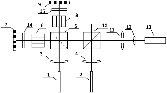
[0016] by figure 1 It can be seen that the method provided by the present invention adopts such as figure 1 The system shown is a fiber mode excitation and coupling system, including two single-mode fibers 1, 2, two collimating lenses 3, 4, two liquid crystal on silicon 7, 9, and two Faraday rotators 6, 8, a polarization beam splitter 5 and a beam combiner 10. The laser light from the single-mode fiber 1 passes through the collimating lens 3, and the laser light from the single-mode fiber 2 passes through the collimating ...


PUM


Abstract

The invention discloses a programmable optical fiber mode stimulation and coupling method, and belongs to the field of optical communication. The programmable optical fiber mode stimulation and coupling method comprises the steps that (1) a light beam given out by a first single-mode optical fiber passes through a first collimation lens; (2) the light beam is divided into polarized light in the horizontal direction and polarized light in the perpendicular direction through a polarization beam splitter, the polarized light in the horizontal direction and polarized light in the perpendicular direction pass through a Faraday activizer, a half-wave plate and silicon-based liquid crystal to be stimulated to form high-order mode light beams in sequence; (3) the high-order mode light beams are respectively reflected to be horizontally input into the polarization beam splitter, beam combination is carried out, and a combined light beam of a high-order mode is output; (4) the combined light beam is input into a beam combiner in the horizontal direction, a light beam given out by a second single-mode optical fiber passes through a second collimation lens, and is input into the beam combiner in the perpendicular direction, and the light beam and the combined light beam which is input into the beam combiner, is input into the beam combiner in the horizontal direction and is of the high-order mode are together output from the beam combiner, and enter a few-mode optical fiber after being coupled through a focusing lens. Due to the facts that phase modulation is carried out on a light field through the silicon-based liquid crystal, and the voltage of each pixel of the silicon-based liquid crystal can be controlled through programming, high-accuracy selective stimulation of any high-order mode can be achieved, and meanwhile the function of polarization multiplexing and the function of mode multiplexing can be achieved.

Description

Technical field [0001] The invention relates to a fiber mode selective excitation and coupling technology for a mode multiplexing system in the field of optical communications, in particular to a fiber mode selective excitation and a method for coupling multiple modes to the same few-mode fiber, which is mainly used to selectively excite Advanced mode , And realize the low insertion loss coupling of multiple modes to the same few-mode fiber. Background technique [0002] Compared with the traditional optical fiber communication multiplexing technology, the mode multiplexing technology uses the spatial dimension of the optical field in the optical fiber, and uses multiple modes to transmit different information respectively, so as to achieve the purpose of increasing the capacity of the optical fiber communication system; at the same time, due to the increase The effective area of ​​the fiber core reduces the damage to the optical signal caused by the nonlinearity of the fiber to...

Claims


Application Information

Patent Timeline
IPC IPC(8): G02B6/32G02B27/28H04J14/02
Inventor 于大伟沈平付松年唐明周金龙朱冬宏
Owner JIANGSU JINDI ELECTRONICS TECH
Why Eureka
Try Eureka