
Intermediate booster pump station

A pumping station and pressure technology, which is applied in the field of technical measures to improve the water supply capacity of tap water intermediate booster pumping stations per unit time, and can solve the problems of inability to meet requirements, increased power consumption of intermediate booster pumping stations, and low pressure.

Inactive Publication Date: 2013-12-18
SHANGHAI PANDA MACHINEGRP CO LTD
View PDF6 Cites 4 Cited by
  • Summary
  • Abstract
  • Description
  • Claims
  • Application Information

AI Technical Summary

Problems solved by technology

[0002] The existing tap water intermediate pressurized pumping station generally adopts the pool plus frequency conversion mode. The water supply volume of the water plant to the intermediate pressurized pumping station is generally designed according to the daily water supply volume. The water supply volume of the water plant is divided by the daily water supply volume. Supply the intermediate pressurized pump station, but the intermediate pressurized pump station has peaks and valleys when supplying water to users (for example, the designed daily water supply of the water plant is 10,000 tons, and the hourly flow rate of the pump unit is 416 tons, but the user's water consumption may be 50~ 800 tons), the inflow of water cannot meet the requirements at peak times, and there is a surplus of water at low peak times, resulting in the phenomenon that the pressure of users is low or even useless at peak times, and the water supply of the water plant cannot be supplied. The water pressure of the pressurized pumping station is all released to normal pressure, which increases the power consumption of the intermediate pressurized pumping station

Method used

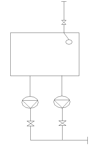

Image

  • Intermediate booster pump station
  • Intermediate booster pump station

Examples


Embodiment Construction

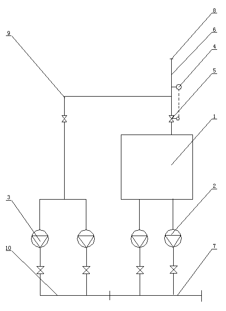
[0008] Such as figure 2 The shown intermediate pressurized pumping station consists of: regulating pool 1, atmospheric pressure pump group 2, superimposed pump group 3, pressure detection device 4, regulating control valve 5, connecting pipe and frequency conversion control cabinet (not shown in the figure) Composition, the pressure detection device 4 and the adjustment control valve 5 are installed on the water inlet pipe 6 of the regulating pool 1, the water inlet pipe 6 is provided with a nozzle 8 connected to the water plant, and the water inlet pipe of the normal pressure pump group 2 is connected to the regulating pool 1, The water outlet of the normal pressure pump group 2 is connected to the water outlet main pipe 7, the water inlet of the superimposed pump group 3 is connected to the water inlet pipe 6 through the pipeline 9, and the water outlet pipe 10 of the superimposed pump group 3 is connected to the water outlet main pipe 7 of the normal pressure pump group , ...


PUM


Abstract

A pressure detection device and an adjustment control valve are installed at a water inlet pipe of a water pool of an intermediate booster pump station, incoming water after passing through a control valve then enters into an adjusting water pool, the water inlet pipe is connected to an overlying pump group, and a water outlet pipe of the overlying pump group is connected to a water supply pipe of the intermediate booster pump station. When water inflow can be satisfied with a water supply amount of the intermediate booster pump station, the overlying pump group superimposes pressurized water supply at an inlet water pressure; if the water inflow is higher than the water flow used by a user, the pressure at the opening of the water inlet pipe increases accordingly; the pressure detection device when detecting that the pressure at the opening of the water inlet pipe rises to a set pressure value switches on the adjustment control valve to enable excessive water to flow into the adjusting water pool; the opening degree of the adjustment control valve is increased along with the increasing pressure; during the water use peak, the adjustment control valve is switched off, a normal pressure pump group of the intermediate booster pump station is put into use to supply the pressurized water in the adjusting water pool and the water pressurized by the overlying pump group to a user. Therefore, the intermediate booster pump station increases water supply capability of the pump station in the water use peak and is satisfied with the requirements on the pressure of the water used by the user.

Description

technical field [0001] The invention relates to a technical transformation measure for improving the water supply capacity of an intermediate pressurized pump station, in particular to a technical measure for improving the water supply capacity per unit time of an intermediate pressurized pump station for tap water. Background technique [0002] The existing tap water intermediate pressurized pumping station generally adopts the pool plus frequency conversion mode. The water supply volume of the water plant to the intermediate pressurized pumping station is generally designed according to the daily water supply volume. The water supply volume of the water plant is divided by the daily water supply volume. Supply the intermediate pressurized pump station, but the intermediate pressurized pump station has peaks and valleys when supplying water to users (for example, the designed daily water supply of the water plant is 10,000 tons, and the hourly flow rate of the pump unit is 4...

Claims


Application Information

Patent Timeline
Patent Type & Authority Applications(China)
IPC IPC(8): E03B11/16
Inventor 池学聪谭红全
Owner SHANGHAI PANDA MACHINEGRP CO LTD
Learn More