Centrifugal fan with axial flow wind direction

A technology of centrifugal fan and axial flow direction, which is applied to the components of pumping devices for elastic fluids, radial flow pumps, non-variable pumps, etc., and can solve the problem of small size, hindering flow field, and setting space restrictions And other issues

Active Publication Date: 2013-12-18
DELTA ELECTRONICS INC
View PDF7 Cites 10 Cited by
  • Summary
  • Abstract
  • Description
  • Claims
  • Application Information

AI Technical Summary

Problems solved by technology

The rotating area of ​​the fan blade 21 of the axial flow fan 20 is equal to the cross-sectional area of ​​its channel. If components are installed within this range, the flow field will be hindered. Therefore, the preferred electronic component installation position in the casing 10 is the center of the axial flow fan 20 However, the volume of the fan hub 22 of the general axial flow fan 20 is not large, and the installation space of the electronic components in the casing 10 is limited.
To achieve channel optimization, it is necessary to configure a larger axial flow fan 20 to obtain a larger fan hub 22 area; if an axial flow fan 20 of a general size is configured, the channel will be blocked by electronic components

Method used


Image

  • Centrifugal fan with axial flow wind direction
  • Centrifugal fan with axial flow wind direction
  • Centrifugal fan with axial flow wind direction

Examples


Embodiment Construction

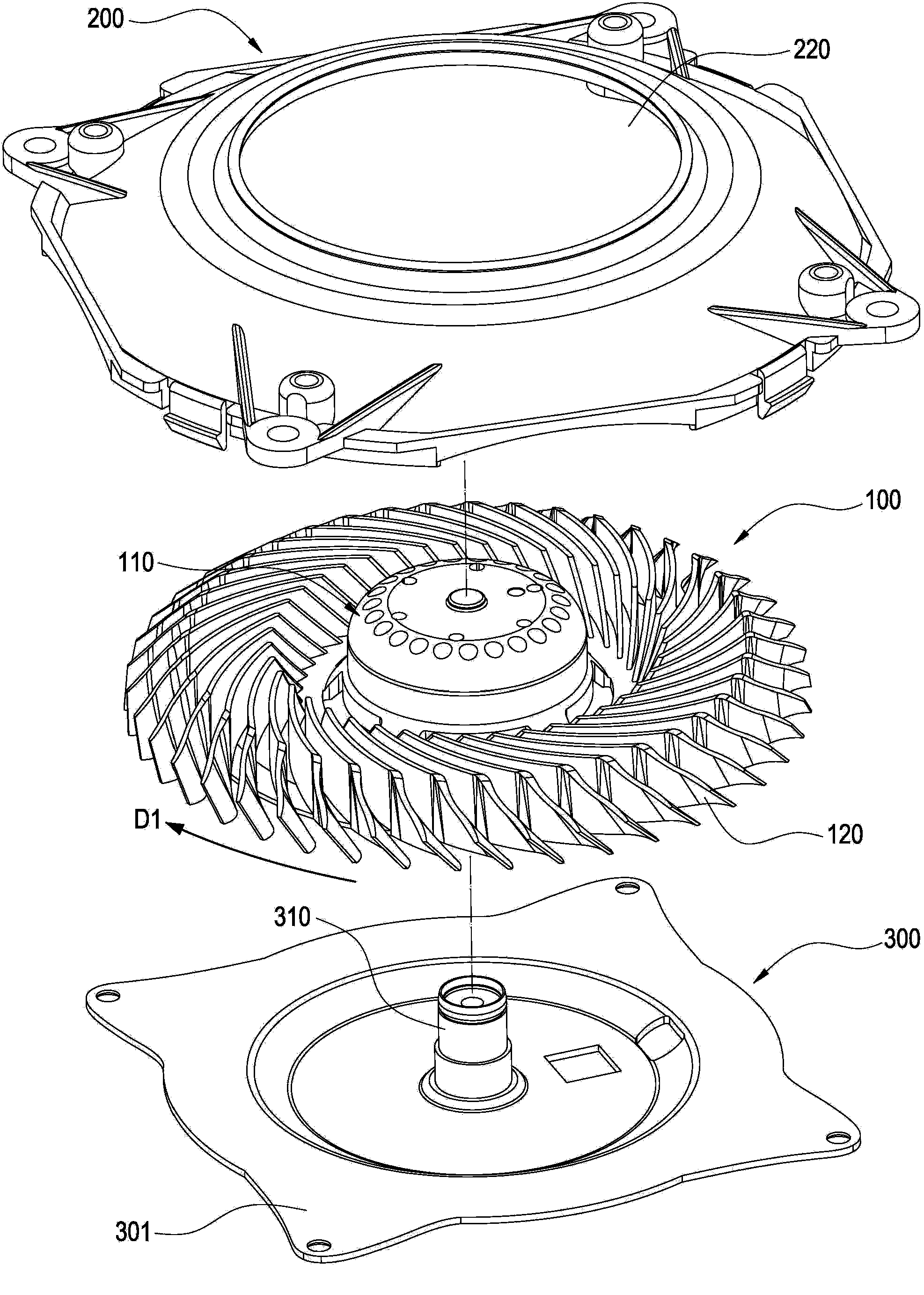
[0051] refer to image 3 and Figure 4 , The first embodiment of the present invention provides a centrifugal fan with an axial flow direction, which includes a centrifugal fan wheel 100 , a casing 200 and a fixing seat 300 .

[0052] refer to Figure 3 to Figure 5 , the centrifugal fan wheel 100 includes a rotating core structure 110 and a plurality of centrifugal fan blades 120 . The rotating core structure 110 includes a fan hub 111 and a bottom plate 113. The fan hub 111 is preferably a cylindrical shell (but the present invention is not limited thereto, for example, the fan hub 111 may also be a conical shell), and the fan hub 111 is preferably a cylindrical shell. The inner side of the hub 111 has a rotating shaft 112, the rotating shaft 112 is preferably arranged along the axial direction of the fan hub 111; the centrifugal fan wheel 100 rotates along the rotating shaft 112 towards a forward rotation direction D1; Along the radial extension of the fan hub 111 (or the...


PUM


Abstract

A centrifugal fan with an axial flow wind direction comprises a centrifugal fan wheel and a housing. The centrifugal fan wheel is provided with a rotary core structure and a plurality of centrifugal fan blades arranged around the rotary core structure. An annular wind guiding face is arranged inside the housing, surrounds the rotary core structure and shields the centrifugal fan blades. Centrifugal air flow on the periphery of the centrifugal fan blades is converted into axial flow air flow through the annular wind guiding face.

Description

technical field [0001] The invention relates to a centrifugal fan, in particular to a centrifugal fan with an axial flow direction. Background technique [0002] Fans are common components in heat dissipation engineering. Common types of fans include centrifugal fans and axial fans. The channel structure of the two is: the centrifugal fan enters the air along the axial direction of the fan wheel and outputs the air along the tangential direction of its rotation; the axial flow fan enters the air along the axial direction of the fan wheel and outputs the air. The flow field characteristics of the two are: the static pressure of the centrifugal fan flow field is large, but its flow rate is small; the static pressure of the axial flow fan flow field is small, but its flow rate is large. [0003] Corresponding to different device spaces, different types of fans need to be installed. For example, narrow and flat spaces such as portable electronic devices are suitable for install...

Claims


Application Information

Patent Timeline
Patent Type & Authority Applications(China)
IPC IPC(8): F04D17/08F04D29/44
CPCF04D17/165F04D25/0613F04D29/281F04D29/4253
Inventor 熊世康陈弘琪陈孟钰
Owner DELTA ELECTRONICS INC
Why Eureka
Try Eureka