Portable air pump

An air pump, portable technology, applied in the direction of variable displacement pump components, pumps, piston pumps, etc., can solve problems such as the inflatable pump not working properly

Inactive Publication Date: 2013-12-25
厉煊
View PDF6 Cites 0 Cited by
  • Summary
  • Abstract
  • Description
  • Claims
  • Application Information

AI Technical Summary

Problems solved by technology

[0003] The technical problem to be solved by the present invention is to provide a portable air pump, which sol

Method used


Image

  • Portable air pump
  • Portable air pump
  • Portable air pump

Examples


Embodiment Construction

[0013] The specific embodiment of the present invention will be further described below in conjunction with accompanying drawing:

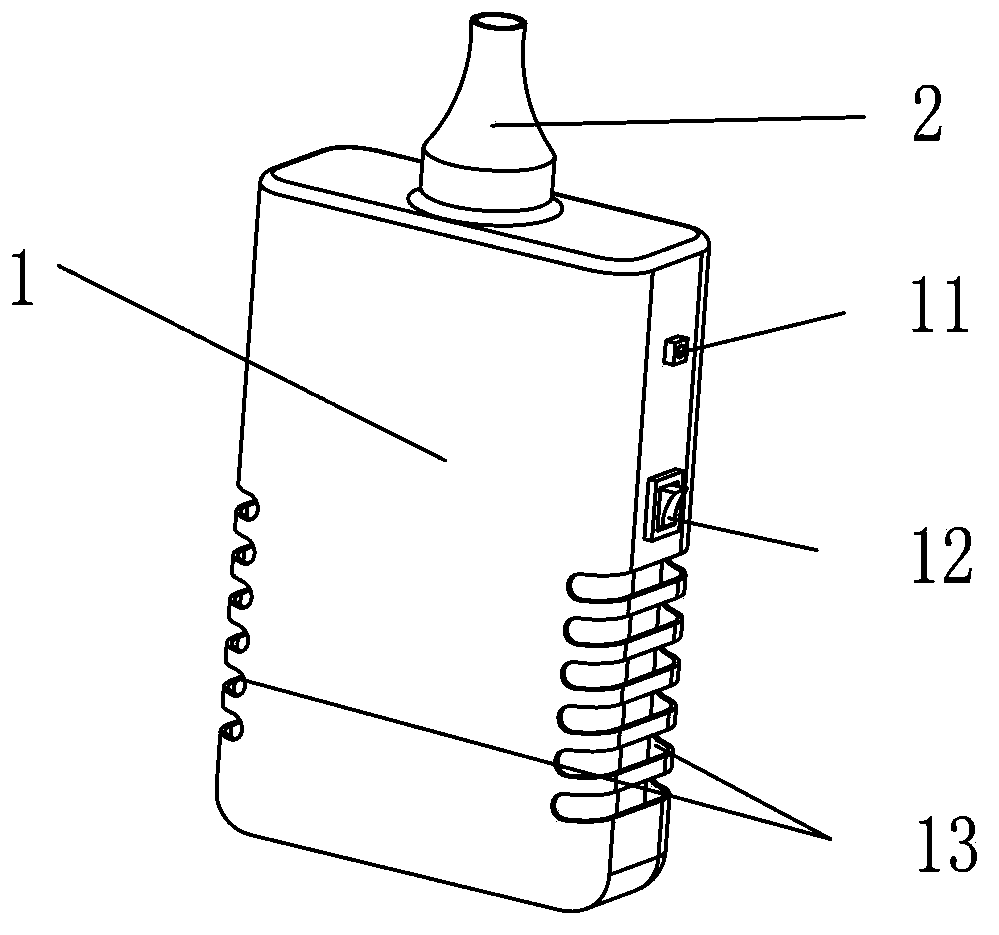
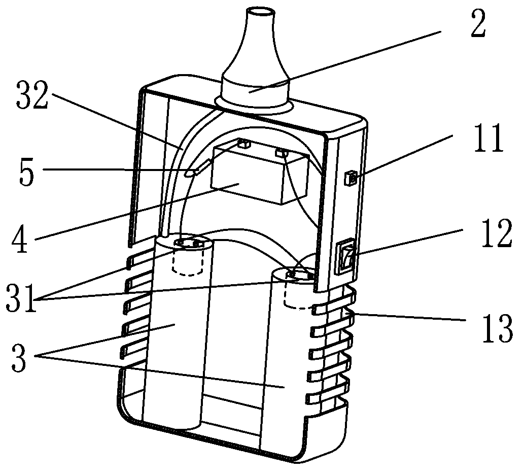
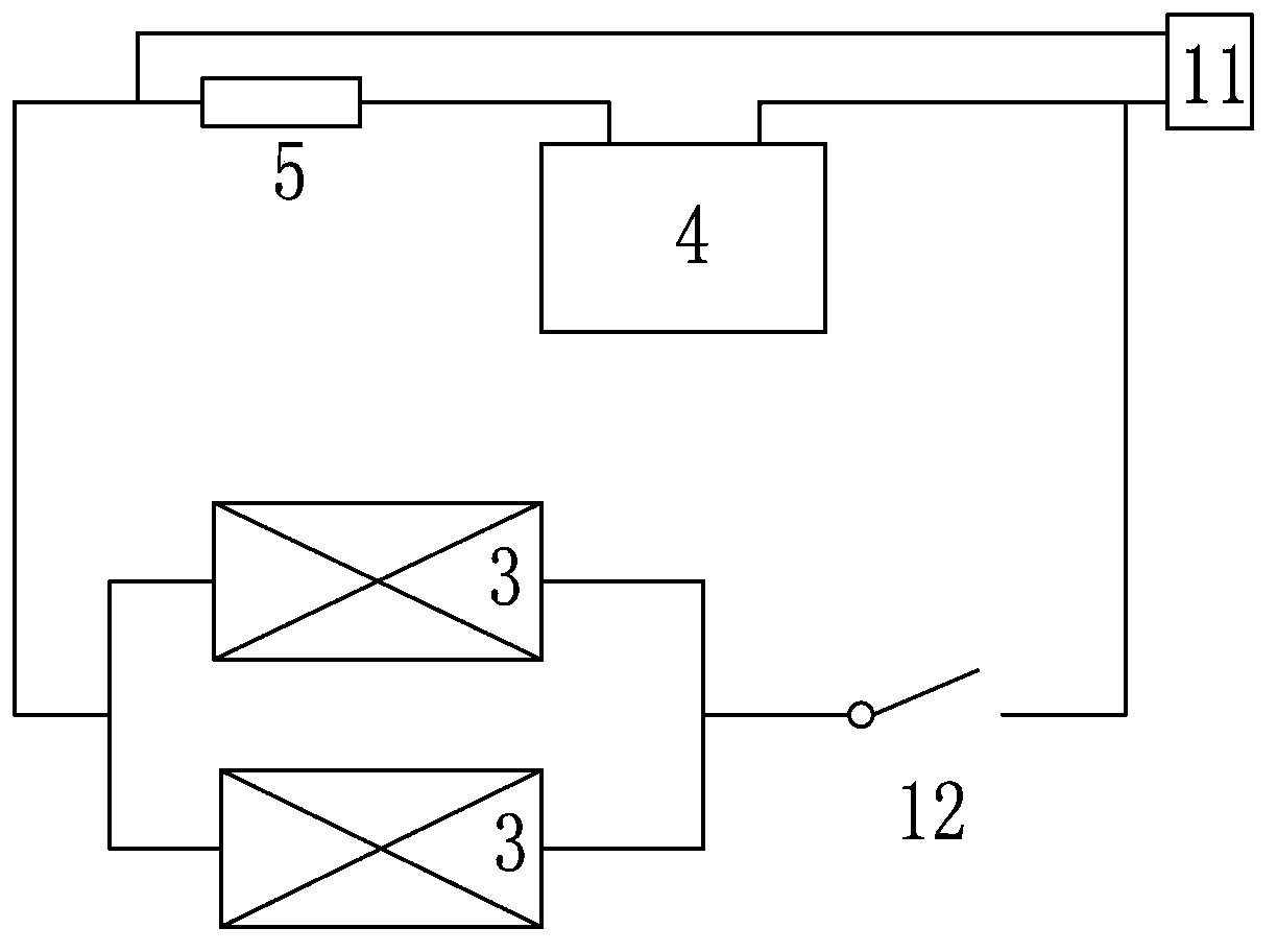
[0014] Such as Figure 1 to Figure 3 As shown, the housing 1 of the air pump in this example is in the shape of a cuboid, which is easier to place. The top of the housing 1 is the air outlet 2, and the shape of the air outlet 2 can be changed as needed to inflate different products. In this example Without too much introduction, there is a charging port 11 on the side of the housing 1. The advantage of setting it on the side is that it does not affect the placement of the air pump even when charging. Inside the housing 1, the charging port 11 is connected by a wire. A storage battery 4 is installed to form a circuit separately. The storage battery 4 is connected to two motors 31 through wires, and the two motors 31 are connected in parallel. When the two motors work together, the inflation speed is faster than that of one motor, and the inflation ...


PUM


Abstract

The invention discloses a portable air pump, which comprises a shell, wherein the shell is provided with an air outlet; a motor is arranged in the shell; during running of the motor, gas is supplied to the air outlet through an air tube; the shell is provided with a charging port; a storage battery is arranged in the shell, and is connected with the charging port through a lead; the storage battery is connected with the motor by using a lead; the charging port can be connected with a power supply to charge the storage battery; and when the external power supply is switched off or is not present, the storage battery can be taken as an internal power supply of the air pump to supply power to the motor.

Description

technical field [0001] The invention relates to an air pump, especially a small air pump. Background technique [0002] At present, air pumps are widely used in people's daily life. Large air pumps usually cooperate with compressors to supply air to industries, while small air pumps are more common in households, especially for inflating some air mattresses, or for some electric vehicles or Inflating bicycle tires, the common structure of this type of small air pump is a shell, with an air outlet and an air inlet on the outside of the shell, and a motor inside, which pumps the gas from the air inlet into the air storage tank when the motor is running , the air storage tank is connected to the air outlet through the air pipe to supply air to the user, but this conventional air pump has one disadvantage, that is, the motor can basically be operated by plugging in the power supply through a wire. It can't work, so if the air pump can have its own power supply, then you won't b...

Claims


Application Information

Patent Timeline
IPC IPC(8): F04B35/04F04B39/12
Inventor 厉煊
Owner 厉煊
Why Eureka
Try Eureka