Supercharge Your Innovation With Domain-Expert AI Agents!

Heat dissipation structure possessing double wind directions

A heat dissipation structure and wind direction technology, applied in cooling/ventilation/heating transformation, etc., can solve the problems of insufficient use, insufficient space, and airflow that cannot be directly blown to the electronic component and its surroundings, etc.

Inactive Publication Date: 2013-12-25
CPUMATE INC +1
View PDF0 Cites 0 Cited by
  • Summary
  • Abstract
  • Description
  • Claims
  • Application Information

AI Technical Summary

Problems solved by technology

[0004] However, limited by the shape of the radiator and the arrangement of the cooling fan, when the fan blows airflow downward or sideways in the cooling direction, and there is not enough space between the radiator and the electronic component, the airflow It cannot be blown directly to the electronic component and its surroundings, so most heat sinks can only use contact conduction to dissipate heat from the electronic component, but for the electronic component that generates a lot of heat in an instant, this kind of heat dissipation The design of the device is no longer adequate

Method used


Image

  • Heat dissipation structure possessing double wind directions
  • Heat dissipation structure possessing double wind directions
  • Heat dissipation structure possessing double wind directions

Examples


Embodiment Construction

[0024] In order to enable the examiner to clearly understand the content of the present invention, only the following descriptions are provided together with the drawings, please refer to them.

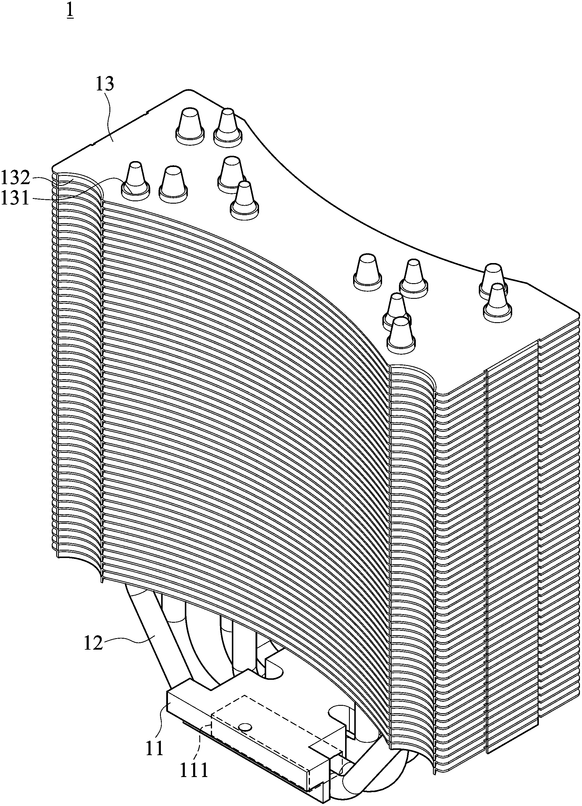
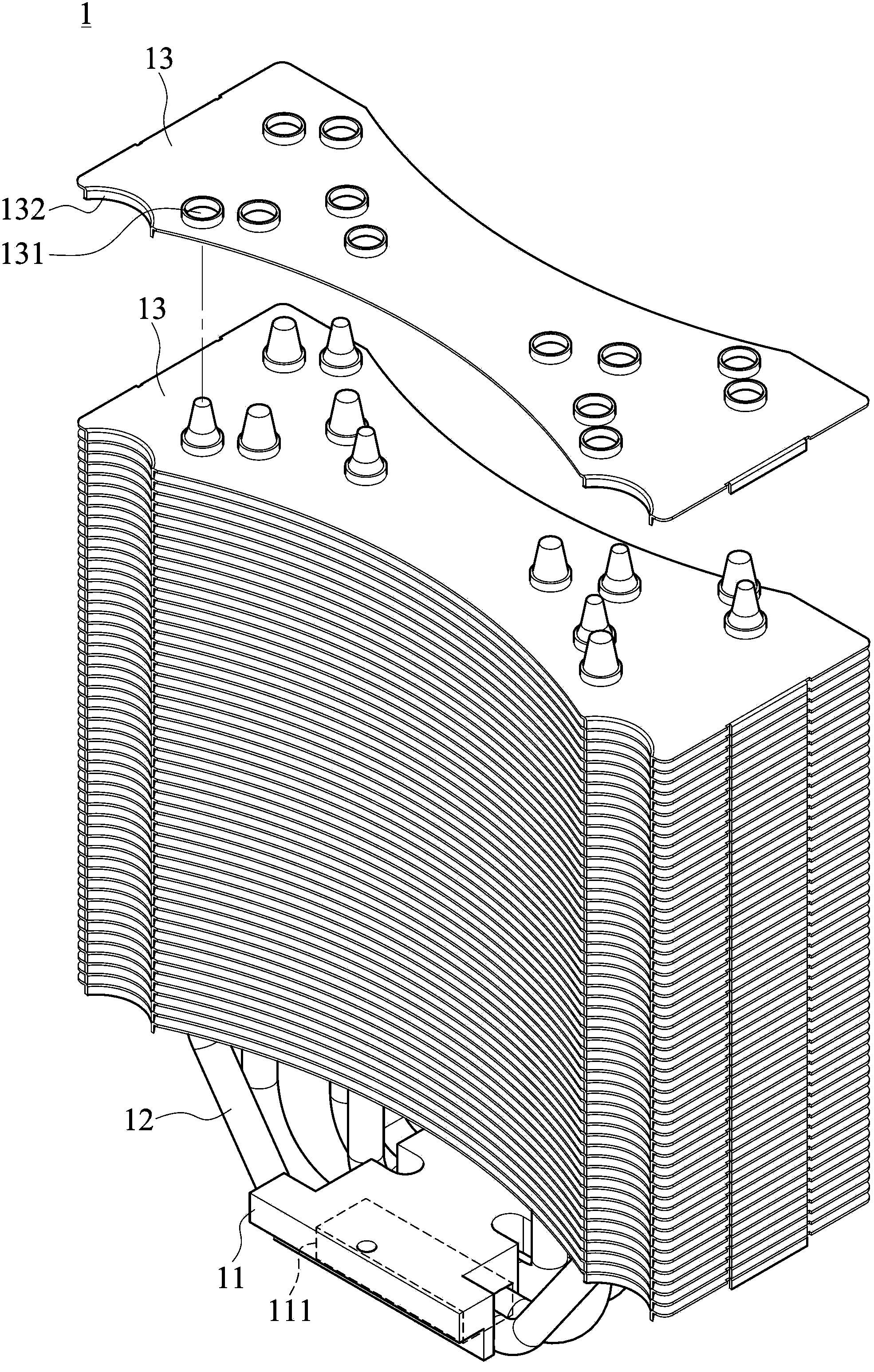
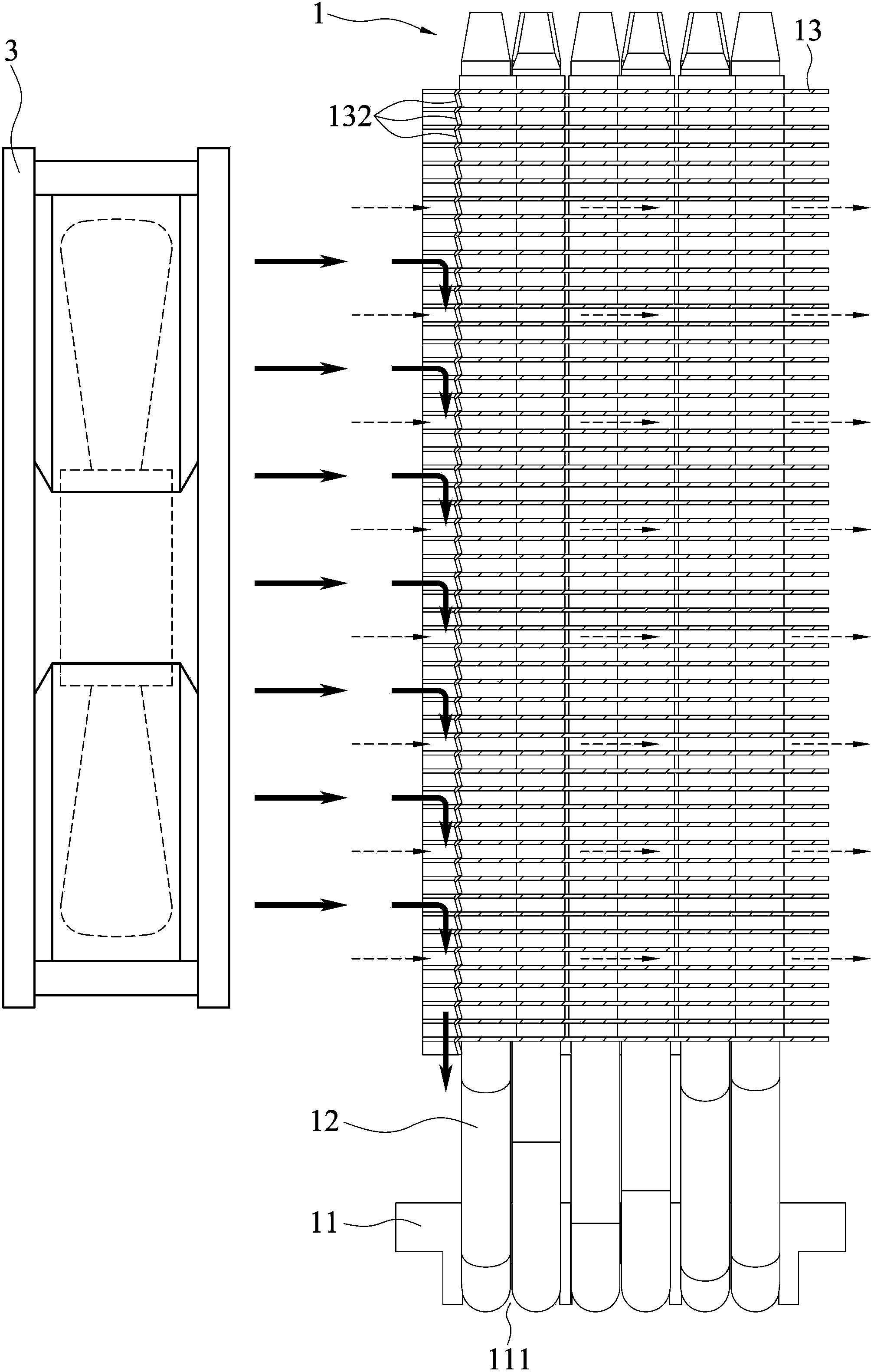
[0025] see figure 1 , 2 Shown is the three-dimensional structure diagram and its three-dimensional exploded view of the preferred embodiment of the present invention. As shown in the figure, the heat dissipation structure 1 with dual wind directions of the present invention is for installation on an electronic component 2, and a wind source 3 is provided on one side thereof. The heat dissipation structure 1 with double wind directions includes a base 11, multiple A branch heat pipe 12 and a plurality of cooling fins 13 .

[0026] The base 11 is a rectangular block-shaped structure made of a heat-conducting metal material such as aluminum or copper through casting or stamping, and one side thereof is disposed on the electronic component 2 . Furthermore, the base 11 can be provided w...


PUM


Abstract

A heat dissipation structure possessing double wind directions comprises a pedestal, a plurality of heat pipes and a plurality of cooling fins. The heat pipes are extended from one side of the pedestal. The cooling fins are arranged on the heat pipes with intervals according to a sequence so as to form a state in which the cooling fins and the pedestal are mutually superposed. At least one flow deflector is arranged on each cooling fin. During assembling, a horizontal diversion channel is formed among the cooling fins. The flow deflector forms a lower diversion channel. During usage, a wind power source is used and the heat dissipation structure possessing the double wind directions is used to carry out sidewall air supply so that one part of wind power diversion takes away heat of the cooling fins through the horizontal diversion channel and another part of the wind power diversion carries out downwards waftage through the lower diversion channel so as to directly dissipate the heat around an electronic component. Heat dissipation efficiency is greatly increased.

Description

technical field [0001] This case belongs to the field of heat dissipation equipment used in electronic devices, especially about a heat dissipation structure with dual air directions, which can generate horizontal airflow and downward airflow at the same time to dissipate heat from an electronic component and its surroundings. Background technique [0002] With the rapid development of science and technology, computer information technology has also been highly developed, which has greatly increased the computing speed of electronic components inside the computer, and the largest heat generation in the computer is the central processing unit (CPU). In order to take into account the stability of its operation And efficiency, and utilize a cooling device to dissipate heat. [0003] Generally, the most common heat dissipation device includes a heat sink and a heat dissipation fan, and the heat sink is selected from a structure with multiple heat dissipation fins stacked on each...

Claims


Application Information

Patent Timeline
Patent Type & Authority Applications(China)
IPC IPC(8): H05K7/20
Inventor 林国仁郑志鸿刘文荣黄俊龙
Owner CPUMATE INC
Features
  • R&D
  • Intellectual Property
  • Life Sciences
  • Materials
  • Tech Scout
  • Unparalleled Data Quality
  • Higher Quality Content
  • 60% Fewer Hallucinations
Learn More