
Wireless router and method of adjusting wireless router signal transmission

A technology for wireless routers and signal transmission, which is applied in the field of communication and can solve problems such as the inability to centrally transmit wireless signals

Inactive Publication Date: 2014-01-01
TP-LINK
View PDF6 Cites 33 Cited by
  • Summary
  • Abstract
  • Description
  • Claims
  • Application Information

AI Technical Summary

Problems solved by technology

[0004] The purpose of the present invention is to provide a wireless router and a method for adjusting the signal transmitted by the wireless router, aiming at solving the problem that the wireless router in the prior art transmits the wireless signal in a fixed direction and cannot automatically transmit the wireless signal to the location of the wireless terminal. question

Method used


Image

  • Wireless router and method of adjusting wireless router signal transmission
  • Wireless router and method of adjusting wireless router signal transmission

Examples


Embodiment 1

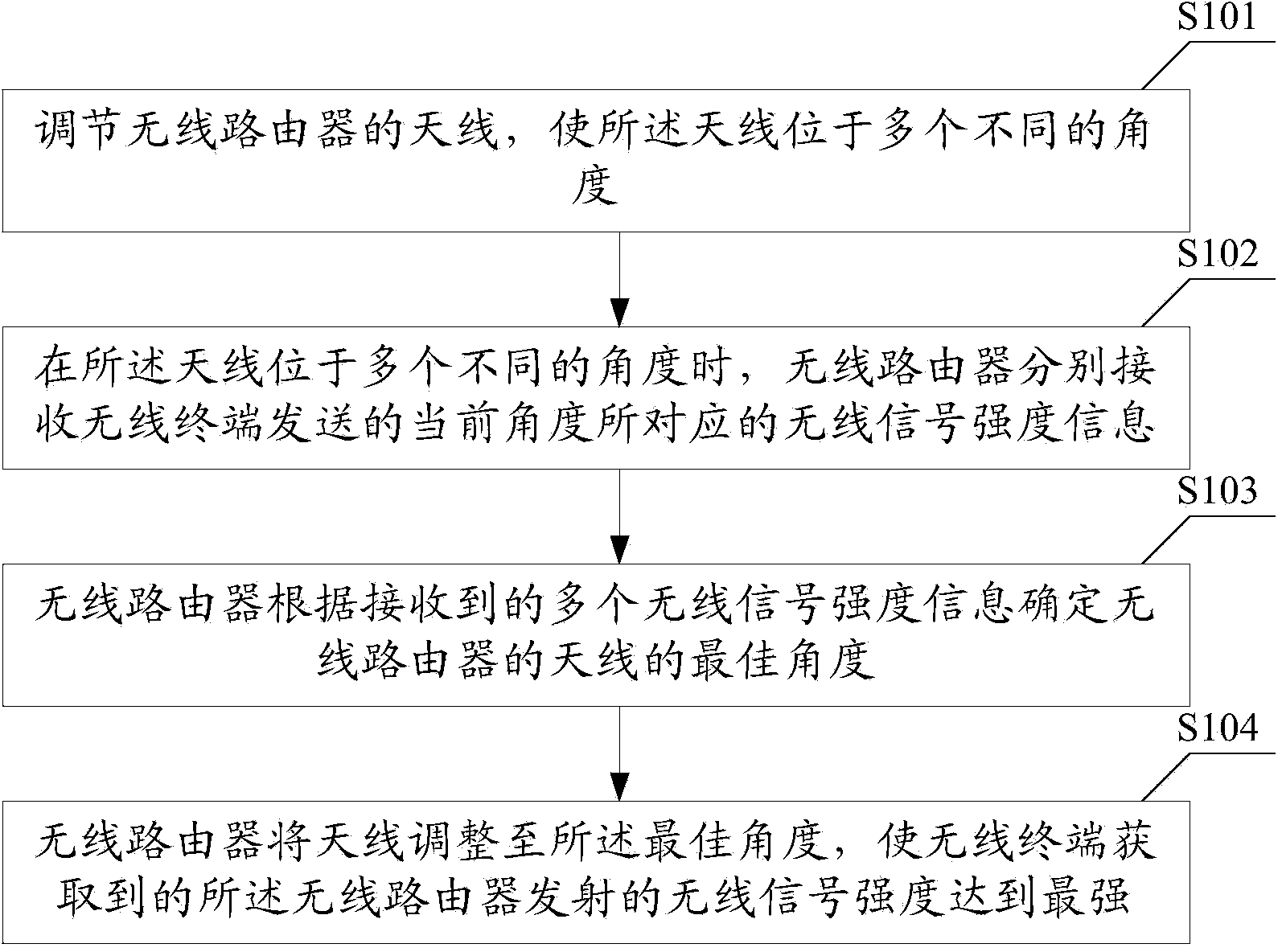
[0021] see figure 1 The method for adjusting a signal transmitted by a wireless router provided in Embodiment 1 of the present invention includes the following steps:

[0022] S101. Adjust the antenna of the wireless router so that the antenna is located at multiple different angles;

[0023] In Embodiment 1 of the present invention, the antenna is a directional antenna.

[0024] S102. When the antenna is located at multiple different angles, the wireless router respectively receives wireless signal strength information corresponding to the current angle sent by the wireless terminal, where the wireless signal strength information is used to identify the wireless signal strength information obtained by the wireless terminal. The strength of the wireless signal emitted by the wireless router;

[0025] In Embodiment 1 of the present invention, S102 further includes the following step: recording the corresponding relationship between the wireless signal strength and the angle a...

Embodiment 2

[0054] see figure 2 , the wireless router provided by Embodiment 2 of the present invention includes: an adjustment module 11, a receiving module 12 and a determination module 13, wherein,

[0055] An adjustment module 11, configured to adjust the antenna of the wireless router so that the antenna is located at multiple different angles;

[0056] The receiving module 12 is configured to respectively receive wireless signal strength information corresponding to the current angle sent by the wireless terminal when the antenna is located at multiple different angles, the wireless signal strength information is used to identify the wireless signal strength information obtained by the wireless terminal The strength of the wireless signal transmitted by the wireless router;

[0057] A determining module 13, configured to determine the optimal angle of the antenna of the wireless router according to a plurality of received wireless signal strength information;

[0058] The adjustm...


PUM


Abstract

The invention is applicable to the communication field, and provides a wireless router and a method of adjusting wireless router signal transmission. The method comprises the following steps: an antenna of the wireless router is adjusted so that the antenna can be located at multiple different angles; when the antenna is located at one of the multiple different angles, the wireless router receives wireless signal strength information, corresponding to the current angle, transmitted by a wireless terminal, wherein the wireless signal strength information is used for identifying wireless signal strength which is acquired by the wireless terminal and transmitted by the wireless router; the wireless router determines the optimal angle of the antenna of the wireless router according to multiple pieces of received wireless signal strength information; the antenna is adjusted to be at the optimal angle through the wireless router. Therefore, the strength of a wireless signal which is acquired by the wireless terminal and transmitted by the wireless router can be the highest.

Description

technical field [0001] The invention belongs to the communication field, and in particular relates to a wireless router and a method for adjusting a signal transmitted by the wireless router. Background technique [0002] A wireless router is a router with a wireless coverage function, which is mainly used for user Internet access and wireless coverage. A wireless router can be regarded as a repeater, which forwards the broadband network signal connected to the wall of the home to nearby wireless terminals, such as laptops, mobile phones that support wifi, etc., through the antenna. [0003] However, the direction in which wireless routers in the prior art transmit wireless signals is fixed, and cannot automatically transmit wireless signals to the location of wireless terminals in a concentrated manner, and cannot make better signals connected to wireless terminals, so the user experience is not good. Contents of the invention [0004] The purpose of the present inventio...

Claims


Application Information

Patent Timeline
Patent Type & Authority Applications(China)
IPC IPC(8): G05D3/12H04W88/08
Inventor 刘长冬欧阳毅高星吴忠陈祥春韩孝龙
Owner TP-LINK
Learn More