Terminal part for storage battery, resin winding terminal for storage battery, manufacturing method thereof, storage battery including terminal part, and automobile equipped with storage battery

A manufacturing method and storage battery technology, applied to small-sized batteries/battery packs, battery pack parts, batteries, etc., can solve problems such as nut fixing methods are not specifically recorded, and achieve the effect of improving work efficiency

Active Publication Date: 2014-01-08
GS YUASA INT LTD
View PDF7 Cites 6 Cited by
  • Summary
  • Abstract
  • Description
  • Claims
  • Application Information

AI Technical Summary

Problems solved by technology

As a result, even when the battery is laid down with the nut insertion hole of the terminal of the GYZ20HL battery facing down, the nut does not fall from the terminal (see Figure 6)" (6th to 11th line of the left column on page 45) , but there is no specific record about the fixing method of the nut

Method used


Image

  • Terminal part for storage battery, resin winding terminal for storage battery, manufacturing method thereof, storage battery including terminal part, and automobile equipped with storage battery
  • Terminal part for storage battery, resin winding terminal for storage battery, manufacturing method thereof, storage battery including terminal part, and automobile equipped with storage battery
  • Terminal part for storage battery, resin winding terminal for storage battery, manufacturing method thereof, storage battery including terminal part, and automobile equipped with storage battery

Examples


Embodiment Construction

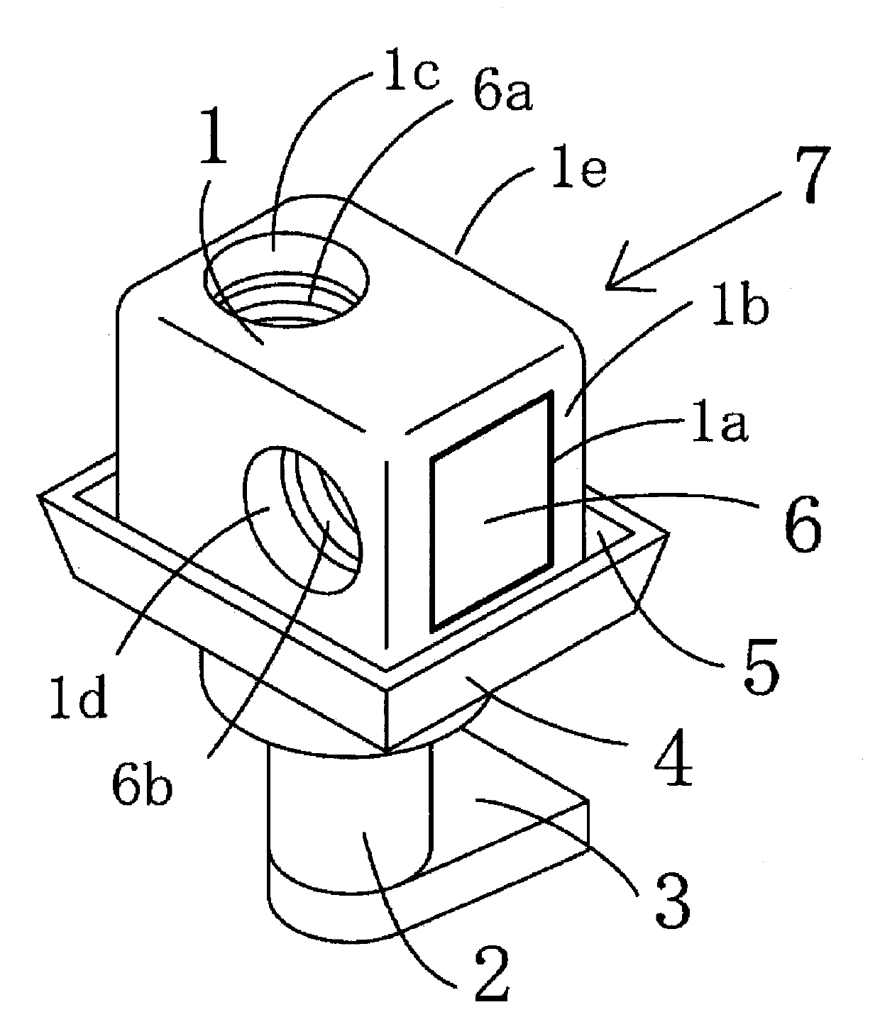
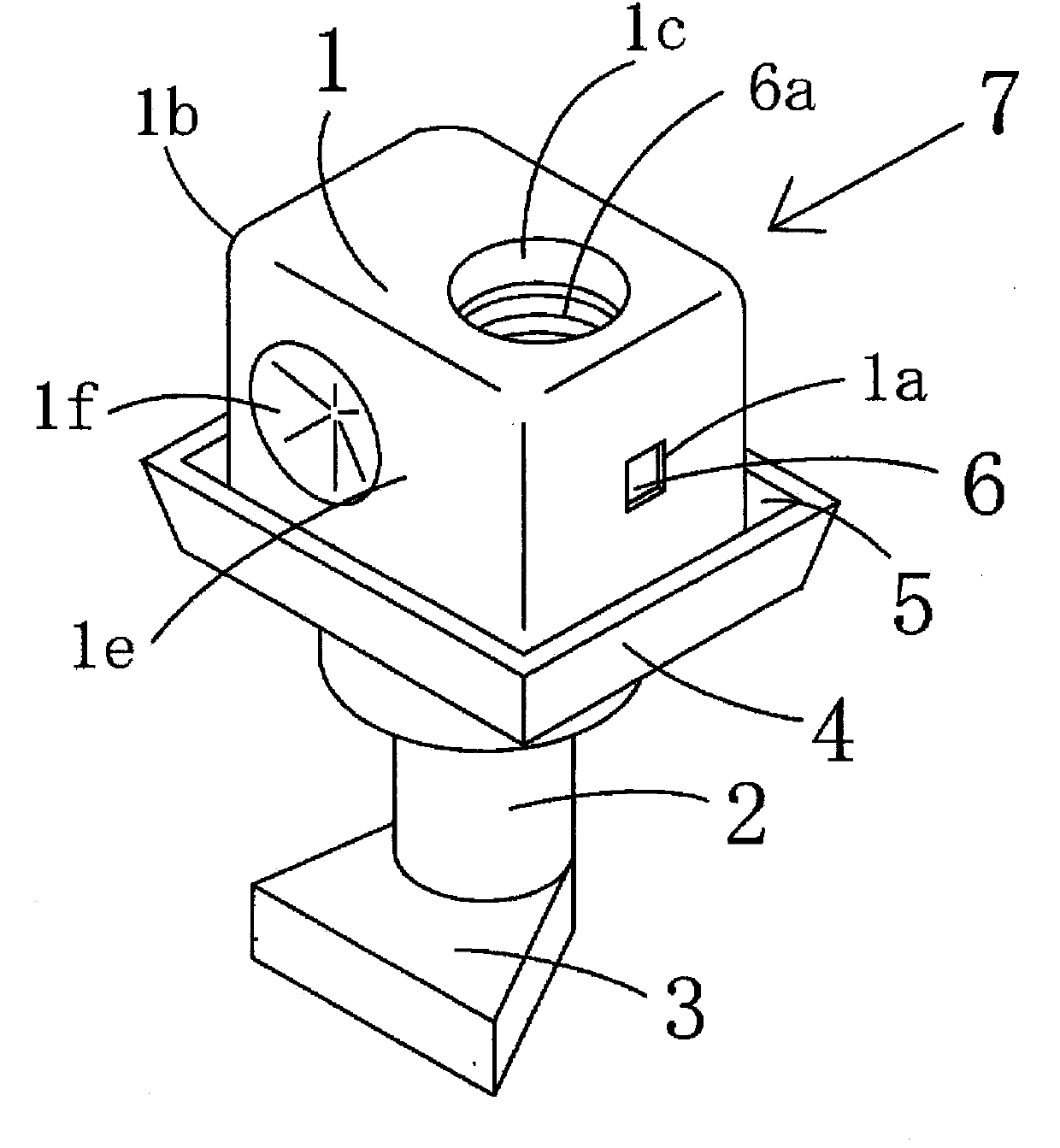
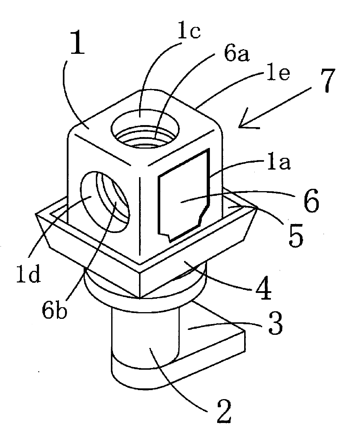
[0067] Embodiment 1 (example applied to the resin winding terminal 7) of the battery terminal part of this invention is shown in FIG.1(a) and FIG.1(b).

[0068] The cuboid battery terminal 1 has a cavity 1a for inserting the nut 6 and an insertion opening 1b, and the cavity 1a for inserting the nut 6 penetrates from the insertion 1b on the right side toward the left side in FIG. 1(a). However, as shown in FIG. 1(b), it is preferable to leave a wall on the side opposite to the insertion 1b so that the nut 6 does not come out. In addition, a bolt insertion hole 1c is drilled from the upper surface toward the cavity 1a, and a bolt insertion hole 1d is drilled from the front surface toward the cavity 1a.

[0069] In Embodiment 1, in order to simultaneously connect external leads at two or more locations, the bolt insertion holes 1c on the upper surface and the bolt insertion holes 1d on the front surface are formed at positions that do not cross each other in the cavity 1a, that i...


PUM


Abstract

The purpose of the present invention is to provide: a storage-battery terminal part with which it is possible to simply and reliably fix a nut to the terminal part so that the nut does not fall; a terminal part with which it is possible to simultaneously select one or more places of an upper surface or front surface to insert a bolt into the nut, even if the nut is fixed to the terminal part when an external lead line is connected to the storage battery; and a storage battery that includes such terminal parts. Provided is a storage-battery terminal part that comprises: a plurality of bolt insertion holes that are drilled from different and / or the same plurality of directions; a nut insertion opening into which the nut is inserted, having at least one screw hole that is cut in at least one direction coinciding with the different and / or same plurality of directions; and a cavity that communicates with the bolt insertion holes and the nut insertion opening, wherein the storage-battery terminal part has a fixing part that deforms the terminal part to fix the nut, in a state in which the nut is inserted from the nut insertion opening into the cavity and at least one screw hole of the nut is made to communicate with at least one of the plurality of bolt insertion holes.

Description

technical field [0001] The present invention relates to a terminal portion for a battery, a resin wound terminal for a battery, a manufacturing method thereof, a battery equipped with a terminal portion, and a motor vehicle equipped with the battery. Background technique [0002] The terminal structure of lead-acid batteries for two-wheeled vehicles often uses resin wound terminals. [0003] As a conventional resin wound terminal, there are known Figure 14 A resin wound terminal as shown (refer to Patent Document 1). exist Figure 14 Among them, symbol 11 is a terminal part made of a rectangular parallelepiped, symbol 12 is a cylindrical pole part, symbol 13 is a plate-shaped base, symbol 14 is a resin part made of polypropylene, polyethylene, etc., and the lower end of the terminal part 11 The upper end of the pole portion 12 is integrally connected, and the lower end of the pole portion 12 is integrally connected with the upper end of the base 13 . On the terminal porti...

Claims


Application Information

Patent Timeline
Patent Type & Authority Applications(China)
IPC IPC(8): H01M2/30H01M50/114H01M50/567
CPCH01M2220/20Y02E60/12H01M2/06H01M2/0242H01M2/305H01R43/00H01M50/114H01M50/567Y10T29/49208Y02E60/10
Inventor 泽亚也北条英次中山恭秀大崎信奥村浩野口胜哉
Owner GS YUASA INT LTD
Why Eureka
Try Eureka