
Crankcase ventilation and vacuum generation

一种曲轴箱、真空的技术,应用在曲轴箱通风、燃烧空气/燃烧-空气处理、燃料中加入非燃料物质等方向,能够解决干扰空气燃料比控制等问题

Inactive Publication Date: 2014-01-15
FORD GLOBAL TECH LLC
View PDF11 Cites 6 Cited by
  • Summary
  • Abstract
  • Description
  • Claims
  • Application Information

AI Technical Summary

Problems solved by technology

Additionally, the required air flow rate can interfere with air-fuel ratio control

Method used


Image

  • Crankcase ventilation and vacuum generation
  • Crankcase ventilation and vacuum generation
  • Crankcase ventilation and vacuum generation

Examples


Embodiment Construction

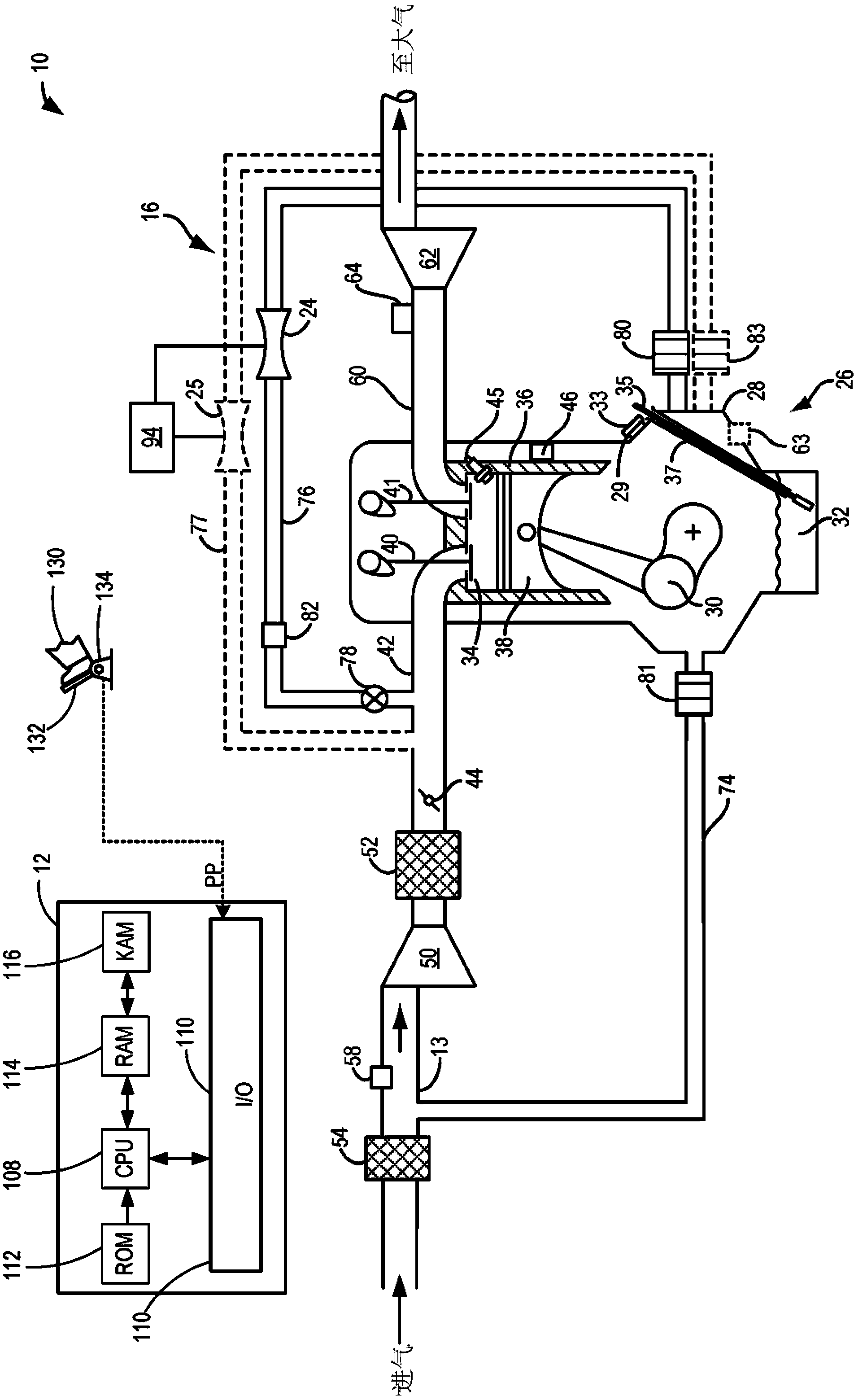
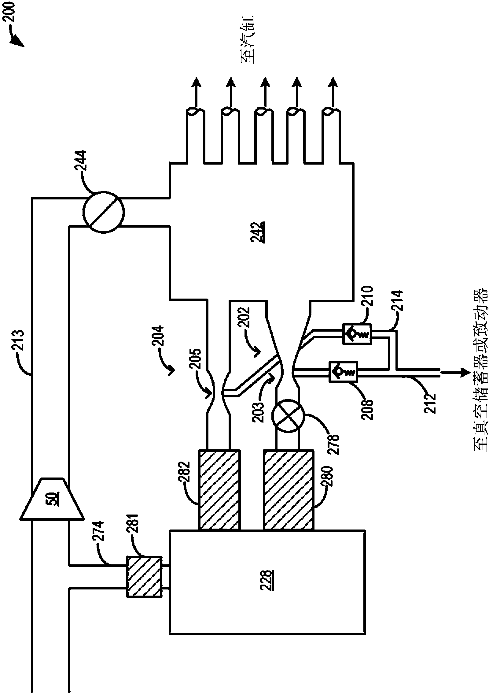
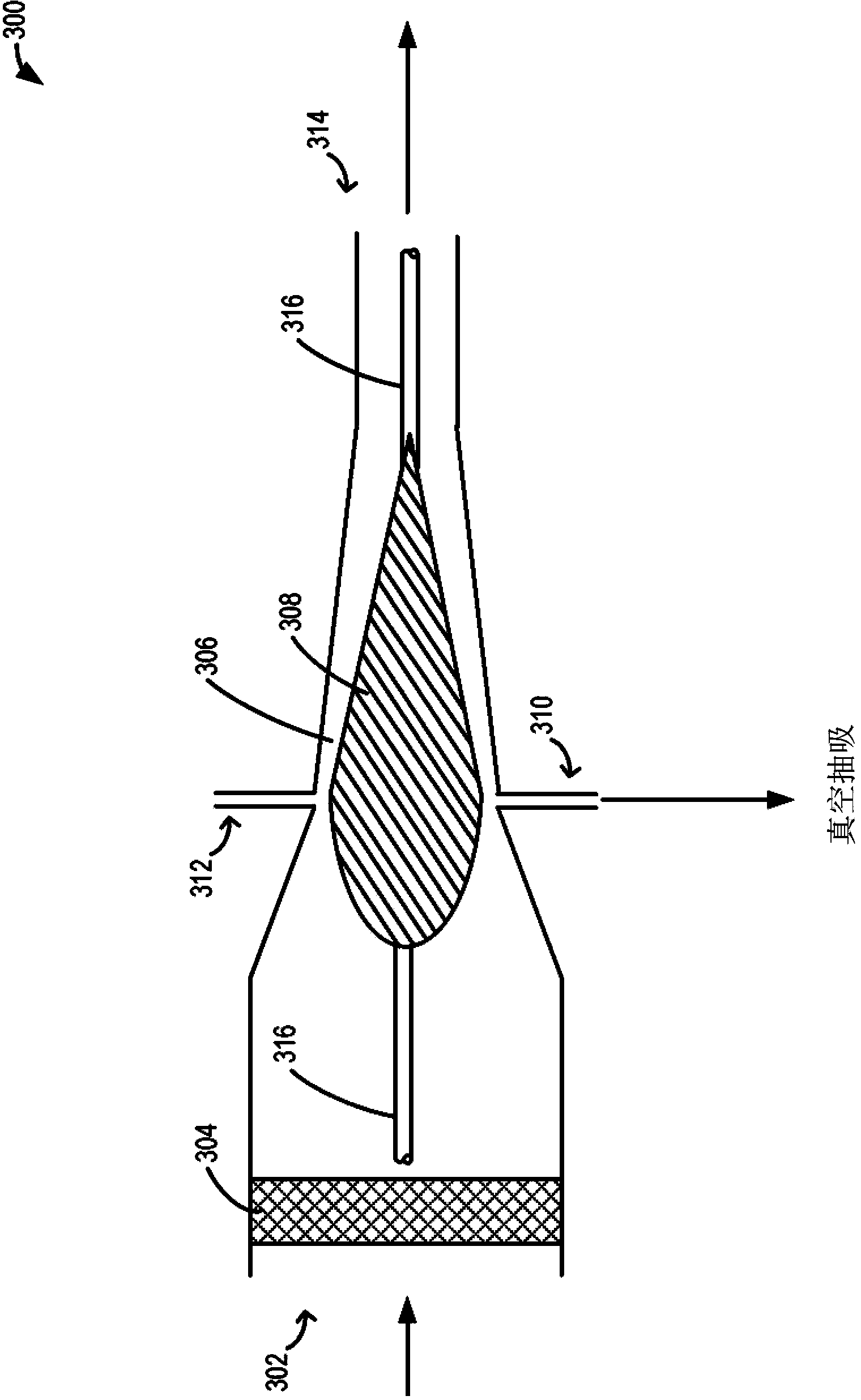
[0027] The following description is concerned with making engine systems such as figure 1 Systems and methods in which air and / or crankcase gases from a positive crankcase ventilation (PCV) line of the engine system shown) flow through an aspirator to create a vacuum. Based on the flow direction in the PCV line between the engine intake manifold and the crankcase, and also based on the aspirator (e.g. Figure 2-3 Aspirator) configuration that directs the airflow through the selected aspirator. The engine controller can be configured to execute control paths such as Figure 4-6 of those, thereby directing airflow through the selected aspirator, and storing the resulting vacuum in a vacuum reservoir for subsequent use. In this way, a vacuum can be created regardless of the direction of flow (of air or crankcase gases) in the PCV line. In addition, vacuum generation can be achieved over a wide range of engine operating conditions.

[0028] refer to figure 1 , illustrates an ...


PUM


Abstract

The invention relates to methods and systems for generating vacuum from crankcase ventilation flow. During both directions of gas flow between an engine intake manifold and a crankcase, gases are directed through one or more aspirators to produce vacuum. The drawn vacuum may then be used to operate various engine vacuum actuators.

Description

technical field [0001] This application relates to the use of crankcase ventilation to create vacuum through the use of a variable venturi during boosted and unboosted engine operation. Background technique [0002] Vehicles may include various actuators that operate using a vacuum source. Vacuum actuators may be used for actuation, applying vehicle brakes, purging fuel tanks, improving engine starting, performing leak tests, and more. Therefore, various vacuum sources can be used on the vehicle. These may include dedicated vacuum pumps as well as vacuum generating ejectors, aspirators and venturis. The engine control system controls the airflow through the ejector / aspirator / venturi, which creates a vacuum which is then used by the various actuators. [0003] Suzuki et al. in US2008 / 0103667 show one exemplary method of directing a gas flow through an ejector to create a vacuum. Therein, an air injector is coupled to a surge chamber upstream of a branched intake manifold ...

Claims


Application Information

Patent Timeline
Patent Type & Authority Applications(China)
IPC IPC(8): F01M13/02
CPCF01M13/023F02B37/00F02M25/06F02M35/10222F02M35/10229Y02T10/12
Inventor R·D·珀西富尔N·D·克里斯普J·N·阿勒瑞
Owner FORD GLOBAL TECH LLC
Learn More